|
KVEC v. 3.19 (30/12/2004, KK-Software, Karl-Heinz Kuhl) |
Readme/What's new |
(10/11/2004, vers. 3.18):
More features and bugfixes for function plotting.
******************************************************************************
* K V E C D O C U M E N T A T I O N *
* *
* +++ KK-Software +++ KK-Software +++ KK-Software +++ KK-Software +++ *
*----------------------------------------------------------------------------*
* Dipl.-Phys. Karl-Heinz Kuhl, Brunnlohestr. 2, 92637 Weiden, Germany *
*----------------------------------------------------------------------------*
* Voice FAX E-Mail *
* +49 961 6340837 +49 961 61455 support@kvec.de *
******************************************************************************
--------!-ABOUT_KVEC------------------------
What is KVEC?
KVEC is a shareware program that allows you to convert raster graphics to
vector graphics. You can freely use it for a trial period of 30 days. After
this period you must register it if you want to continue to use it.
The (unregistered) shareware version can be freely distributed
and copied.
KVEC is very exacting with respect to memory demands. Vectorizing is a
critical process and often leads to a trade off between memory demands
and performance. It is crucial for the performance that your computer has enough
RAM. A minimum of 128 MByte RAM is recommended.
The computing time on a Pentium 500 MHz is in the order of magnitude of
seconds up to minutes, depending on the size and the colour-depth of the
input file.
The selection of values for the switch parameters requires some caution.
Noisy pictures (typical for scanned colour pictures) or pictures with a lot of
very small details should be evaluated with larger 'grit values' and smaller
'quantize values' (explained below).
The output formats DXF and HPGL are not suited for vectorization of coloured
photos or coloured scanned pictures (unless you have lots of GigaBytes left
on your harddisk ;-) the output size would be immense.
Vector representations of images have several advantages in contrast to
rastered block representations: operations like rotation, stretching, morphing
and warping can much easier be performed and one does not have to care about
aliasing and other unwanted effects. The application fields of a good
vectorizer reach from motion estimating in video sequences up to effective
image compression.
Please feel free to contact the author if you have problems with KVEC
or if you find some bugs. KVEC is designed to run on several operating systems
(which have different hardware and graphical environments), therefore this
release of KVEC is a graphic-independend commandline version.
The syntax is quite simple:
KVEC (Inputfile) (Outputfile) [optional switches]
for example:
KVEC test.bmp test.dxf -format dxf
Since version 2.90 wildcards ('*' and '?' ) are allowed for the file names.
Nested subdirectories were not processed when using wildcards.
If the input filename contains wildcards, the outputfilenames will be derived
from the expanded input filenames and get different file suffixes. In the case
of identical input and output filenames KVEC adds an leading underscore ('_')
to the output filename in order to prevent overwriting. Full pathnames can be
specified for input files and output files.
You can also start KVEC using a parameter file (KVEC.PAR) by typing:
KVEC -readpar [filename]
[filename] is the (optional) name of a KVEC parameter file.
The name of the parameter file must be KVEC.PAR (uppercase), if no filename
for the parameter file is specified.
You can use any of the example parameter files in the KVEC package (*.par).
Inputfile is the name of a raster graphic file (Tiff, BMP, PCX, TGA, SGI,
IMG, PNM, JPEG, GIF, WPG, PNG or FAX).
If the name of the input-file is 'null' KVEC will create a 'white noise'
random or other test raster images.
If the name of the input-file is 'vnull' KVEC will create a random
vector image. The properties of this test image depend on
the parameter settings for the '-random' switch.
Outputfile is the name of the desired vector graphic file.
Please note that the name of the output file must be specified with the
filename extension. You cannot omit it.
Note:
KVEC version 1.62 or higher also accepts WMF or ART as input format.
If the input-file has already a vector-format (WMF or ART), most of the
switches will be disregarded. In this case KVEC only performs a format-
conversion from one vector format to another vector format.
KVEC version 1.92 or higher also accepts BMP or TIFF as output format.
If the input-file has already a raster-format, most of the
switches will be disregarded. In this case KVEC only performs a format-
conversion from one raster format to another raster format.
Currently supported vector formats are:
- Windows Metafile, Postscript, AutoCad DXF, HPGL, LogoArt ART,
Adobe Illustrator Format, XFIG, PCS and the KVEC format KVC
SVG(Z) (Scalable vector format), SWF 6.x (Macromedia Flash Format)
DST (Tajiama stick format), HTML
The switches are optional. If you don't specify any switches, the program
chooses a set of parameters which are optimized with respect to the kind of
graphic data. Switches may be abbreviated.
The filenames must be specified before the optional switches.
Some switches however don't require filenames and can be specified immediately
after KVEC. From these switches only one can be specified in each case:
--------!-ehelp-E---------------------------
KVEC -ehelp <topic> Displays help information in English language
--------!-ghelp-E---------------------------
KVEC -ghelp <topic> Displays help information in German language
--------!-info-E----------------------------
KVEC -info: Displays some useful information about KVEC on the screen.
--------!-printform-E-----------------------
KVEC -printform: Automatically generates a registration form. This form can
be sent to the author by E-Mail, Fax, or postal mail in
order to get a registration key. The registration key is
a max. 5 digit number, which allows the user to register
the software and get access to extended features of KVEC.
You will be prompted to select a language. The registration
form will then be generated in your preferred language.
The registration form consists of plain ASCII text.
If you print it out from a text processing program, be
sure that you choose a monospaced font and not a
proportional font. For users from the European countries
a special registration form is available from:
www.kvec.de/files/download/kvec_reg_info_eng/reg_info_eng_europe.htm
--------!-register-E------------------------
KVEC -register: As soon as you get a registration key you can use this
switch to register the program. You will be prompted to
enter your name, the serial-number, and your registration
key. Please type all characters exactly as printed in the
registration confirmation you receive from the author. If
you have entered the information correctly, a message
appears which thanks you for your registration. The
received registration key is valid for updates and future
releases of KVEC.
--------!-readpar-E-------------------------
KVEC -readpar: KVEC reads filenames and additional parameters from a
parameter file (KVEC.PAR) rather than the commandline.
Please note, that the parameter file must reside in the
actual working directory. The parameter file KVEC.PAR
is an ASCI file and can be edited with any text editor.
Comments in the parameter file must be marked by a
#-character and may appear anywhere behind a parameter
or at the beginning of a line.
KVEC -readpar [filename]:
KVEC reads filenames and additional parameters from the
specified parameter file [filename].
--------!-rename-E--------------------------
KVEC *.jpg *.jpg -rename: (only Windows version). This is a very special
switch for renaming multiple files. The renamed filenames
will have the prefix: "high_". This is useful in order to
prepare input files together with the switch "-html".
Generally this will be applied to jpg-files. Here
an example: 'kvec image*.jpg *.jpg -rename'
--------!-writepar-E------------------------
KVEC -writepar: Generates a KVEC parameter file. The user will be prompted
to enter filenames and additional parameters.
The name of the parameter file is always 'KVEC.PAR'
and will reside in the actual directory.
You can add comments behind the parameters you are
promped to input (see above). Parameters always begin with
a leading '-'character. After the parameter file has been
written, the program should be restarted using the
'-readpar' option.
KVEC -writepar [filename]:
Generates a KVEC parameter file with the specified
filename.
--------!-end of writepar-E-----------------
The other switches must follow the input and output filenames:
--------!-antialiasing-E--------------------
-antialiasing <N>: (Only for Vector-Raster-Conversion): Anti-Aliasing will
be applied when rendering.
<N>: 0: no antialiasing, 1: good quality, 2: best quality
<-N>: the same as <N> but will generate more compact lines
--------!-bezier-E--------------------------
-bezier: The output will consist of bezier-curves instead of
straight lines. This allows you to zoom the image without
getting edges. For the output formats which don't support
bezier curves, the bezier algorithm will
be simulated and approximated by polylines.
--------!-bkcolor-E-------------------------
-bkcolor <r> <g> <b>: background color for plotting user-defined functions
(see switch '-function')
--------!-black-E---------------------------
-black: Output color for vectorization is always black
--------!-centerline-E----------------------
-centerline mixed: The effect of this parameter depends on the value of the
parameter -lwidth. (If used together with -centerline,
the meaning of the parameter -lwidth is modified).
Before vectorizing, all detected objects were checked for
its maximal thickness. All objects with a maximal
thickness less than -lwidth were treated as line objects;
all other objects were vectorized in the normal way.
The vectorization of line objects does not result in
border lines around the objects. It produces single lines
which are located along the centerlines of the objects.
The final linewidth of this generated single lines will
be adopted so that the area of the line object is about
the same as the area of the original object.
(this has no effect, if the output format cannot handle
variable linewidths). This is the DEFAULT.
-centerline lines: The same as 'centerline mixed' except that only line
objects will be generated. All other objects will be
discarded.
-centerline off: Turns centerline vectorization off (Default)
--------!-colspace-E------------------------
Selects the internal color space which is used by kvec.
The effect of changing the internal color space will be
noticed when used together with the "colorsep" option
or when bitmap processing is performed ("process" option).
-colspace rgb: RGB color space (default).
-colspace rb: RB color space
-colspace gb: GB color space
-colspace gr: RG color space
-colspace cmyk: CMYK color space
-colspace cy: CY color space
-colspace my: MY color space
-colspace mc: CM color space
Note: If a color space other than RGB or CMYK is selected,
the colors will be changed such that the optical
impression will be quite near to the original image.
--------!-colseparation-E-------------------
Selects the type of color separation. The output file
will only contain the specified color components.
Please note, that for cmyk separation the color space is
also set to the right value.
-colsep rgb: no color separation (default).
-colsep cmyk: no color separation
-colsep rb: extract R and B components
-colsep gb: extract G and B components
-colsep gr: extract R and G components
-colsep cy: extract C and Y components
-colsep my: extract M and Y components
-colsep mc: extract C and M components
-colsep rr: separate R color
-colsep gg: separate G color
-colsep bb: separate B color
-colsep cc: separate C color
-colsep mm: separate M color
-colsep yy: separate Y color
Note: It is useful to produce a gray-scale output file
for single component color separation. This can be
achieved by using the "-black" option together with colsep.
--------!-coord-E---------------------------
Specifies the type of internal scaling of coordinates
-coord optimize: coordinates may be rescaled in order to improve resolution
(default)
-coord pixel: the original pixel coordinate system will be used
--------!-dimension-E-----------------------
-dimension N: Specifies the maximum extension (in x- or y-direction)
of the generated output image. Default: 512 pixels.
IMPORTANT: This parameter will only be evaluated, if
the input file is of vector type (or 'null').
--------!-xdim-E----------------------------
-xdim N: Specifies the maximum extension (in x-direction)
of the generated (raster) image. Default: original value
--------!-ydim-E----------------------------
-ydim N: Specifies the maximum extension (in y-direction)
of the generated (raster) image. Default: original value
--------!-dither-E--------------------------
-dither off: Turns dithering off (Default)
-dither linear: Turns dithering on
Note: Dithering will only performed, if the output format
is a raster format.
--------!-drcolor-E-------------------------
-drcolor <r> <g> <b>: drawing color for plotting user-defined functions
(see switch '-function')
--------!-dst-E-----------------------------
-dst dist <N>: specifies the stitch distance in 0.1 mm
-dst width <N>: specifies the line width in 0.1 mm
-dst fill hollow: Colored areas will not be filled
-dst fill hatch: Generates cross-hatched lines (see hatch1 ...), default
-dst fill zickzag: Generates zickzag lines
--------!-dxfopt-E--------------------------
-dxfopt type 2dim: Generates 2-dimensional coordinates (if the output format
is DXF. (Default)
-dxfopt type 3dim: Generates 3-dimensional coordinates (if the output format
is DXF.
-dxfopt form unix: adds only <LF> (line feed) at line ends (default)
-dxfopt form dos: adds <CR> <LF> at line ends
--------!-fill-E----------------------------
The fill parameters specify how the generated polylines/polygons will be
interpreted:
-fill solid: Polygons are always closed (i.e. the last point of a
vector is identical with the first point). The Polygons
are filled with individual colors (DEFAULT). The sort
parameter should not be 'min' in this case because the
larger Polygons would cover and hide the smaller ones.
-fill line: Output consists of polylines with individual colors. The
polylines are not closed. This is the preferable fill
parameter if the outputfile is generated for a pen-plotter.
The plotter pen will never plot more than one color one
upon another. The layout will depend on the sort order
specified with the 'sort' switch. With the switches
'reduce' and 'smooth' you can once more refine the layout
of the output.
-fill contour: The same as '-fill solid', however the interiors of the
polygons remain 'hollow'. Lines with different colour
can cover each other. The layout will depend on the
sort order specified with the 'sort' switch.
--------!-font-E----------------------------
-font: KVEC generates (before vectorization) an optimized set
of parameters, which is suited for vectorization of
dark colored text on a clear background. All objects
get a unique 'dark' color. Sort order "local" is
automatically turned on for generation od sub-polygons.
--------!-format-E--------------------------
The format parameters specify the output format:
(Please note that KVEC can also determine the output format by parsing the
file suffix from the output filename, if you don't specify a output-format)
-format wmf: Output format is Windows Metafile format, *.WMF
-format amf: Output format is ALDUS WMF Metafile (default), *.WMF
-format emf: Output format is Enhanced Windows Metafile format, *.EMF
-format ps: Output format is Postscript level 2, *.PS
-format eps: Output format is Encapsulated Postscript level 2, *.EPS
-format dxf: Output format is AutoCad DXF, *.DXF
-format hpgl: Output format is HPGL, *.HPG or *.PLT
-format art: Output format is ART LogoArt (OS/2-graphics program), *.ART
-format ai: Output format is Adobe Illustrator, *.AI
-format bmp: Output format is Windows Bitmap, *.BMP
-format tiff: Output format is Tiff, *.TIF
-format zyxel: Output format is ZYXEL FAX
-format pfax: Output format is PowerFax
-format kvc: Output format is KVEC vector format
-format xfig: Output format is XFIG vector format (Linux Drawing program)
-format pcs: Output format is Pfaff PCS vector format
-format dst: Output format is Tajiama stick format
-format wav: Output format is WAV
-format svg: Output format is SVG (scalable Vector Graphics)
-format svgz: Output format is SVGZ (compressed scalable Vector Graphics)
-format swf: Output format is SWF (Macromedia Flash MX Format)
The Macromedia Flash MX Editor only accepts special
settings which can be controlled by the switch 'winding'
-format png: Output format is PNG (Portable Network Graphics)
-format html: (only windows version)
This is not a real output format, but a switch for a
very special application: Assume you have a lot of
jpg-files and you want to generate a set of html-files which
allow you to view all these files in a convenient way.
Kvec will generate a seperate html-file for each individual
image. A html-file called "directory.htm" will also be
generated, which refers to the individual html-files.
Each image can be viewed in up to 3 resolutions:
low, medium, and high. Therefore, each image must exist in
3 versions (e.g. high_test.jpg, mid__test.jpg, low__test.jpg).
The following command will perform the whole procedure
(please note, that the input filename must be specified
without the leading 'high_'. You can use kvec together with
the switch '-rename' in order to add the 'high_'-prefix to
ti whole set of input files.
kvec test*.jpg *.htm -xdim 100
Assume we have 100 files with filenames that begin with
'high_' (high_test01.jpg, high_test02.jpg..). KVEC will
generate 100 html files with links to 100 preview files
(named low__test01.jpg, low__test02.jpg...)
The preview images can be viewed in the file directory.htm,
which refers to 100 html files (high_test01.htm,
high_test02.htm... Each individual html file contains a
medium-resolution image (mid__test01.jpg, mid__test02.jpg)
and a link to the high-resolution version: high_test01.jpg,
high_test02.jpg...). Please note that all three sets of
jpg-files must exist, before kvec can be execute this way.
The 3 types of prefixes must be exactly:
'high_', 'mid__' and 'low__' (5 chars length).
The parameter '-xdim <N>' can be used to contol the size of
the table which contains the low-resolution preview images.
If you want a nice background for the html files, you should
copy the file cdbkgnd.jpg into the directory containing the
html files.
--------!-function-E------------------------
-function ...: (see also: '-nstep', '-bkcolor', '-drcolor', '-xmin',
'-xmax', '-ymin', '-ymax', '-tmin', 'tmax', -lwidth')
This switch is not for processing image files.
The function switch lets KVEC generate plots of mathematical
functions, which can be entered right after the function-
keyword. The definition of math. function also includes
the definition of user-specified constants. As the definition
of functions and variables can be very long, it is not
recommended to enter all this values on the commandline.
It is much more practicable to enter all the definitions in
a KVEC parameter file.
The strings following the '-function' keyword are interpreted
as a C-style written definition of up to 8 functions and
100 Variables. The keyword 'endfunc' terminates
the function definition. Assignments of variables (constants)
must precede the definition of functions! Thus, variables can
not be initialized with function results.
Some restrictions apply:
Functions must follow one the following naming conventions:
f?(argument) ('?' can be any alphanumeric char)
(argument can be one of: x,y,z,t,i)
x?(argument) y?(argument) ('?' any alphanumeric char)
(parametric representation)
r?(phi-argument) ('?' can be any alphanumeric char)
(argument must be: p)
(representation in polar-coordinates)
Here a few examples: f1(x)=sin(x); fa(t)=cos(t); (allowed)
fabc(x)=x; (not allowed)
f1(x) = cos(x); (not allowed)
f2(x)=SUM(n=1,100,x^n/n!); (allowed)
x3(t)=cos(t); y3(t)=sin(t); (allowed)
y(x)=exp(x); (not allowed)
x1(i)=kv_primes[i]; y1(i)=i; (allowed)
r1(p)=0.5*p; (allowed)
Each statement ends with a ';' Within a statement, no blanks
or other white-spaces are allowed. Statements however can be
seperated by any white-space chars.
Please note that max. five different functions are allowed.
The file names must exactly start with an 'f' followed by any
alphanumeric char. The function argument must be one of:
'x', 'y', 'z', 't' or 'p' (in case of polar-coordinates).
Expressions can be nested by braces '(', ')'. Constants may
be defined like this (examples):
ABC=1.234; SQ2=1.414; ...
The following operators are allowed:
'+' Addition or unitary '+'
'-' Subtraction or unitary '-'
'*' Multiplication
'/' Division
'^' Raising to a power
'!' Factorial (can also be applied to expressions)
'SUM' Summation. Syntax: SUM(n=<start>,<end>,<func>);
e.g.: SUM(n=1,100,x^n/n!);
'PROD' Products. Syntax: PROD(n=<start>,<end>,<func>);
(There can be only one loop-variable in the SUM or PROD
statements, loop-variables must be initialized with constants).
All functions defined in the C-ANSI standard can be used.
This covers most of the elementary mathematical functions.
The following higher mathematical functions can also be used
(at the moment, this set will be expanded):
gamma_r(x); (real Gamma Function)
PI_func(x); (no. of primes up to x)
nth_prime(x); (returns the n-th prime number)
nth_mprime(x); (returns n-th Mersenne prime-exponent)
nth_zzero(); (returns n-th zero of the zeta-function)
(only available in special MATH KVEC version)
IsPrime(x); (returns 0.0 or 1.0, in case of prime)
riemann_r(x); (real Riemann Function)
sigma(x); (no. of divisors function)
zeta_r(x); (real Zeta Function)
zeta_cr(x); (real Zeta-Function along crit. strip)
zeta_ci(x); (imaginary Zeta-Function along ")
KVEC offers also predefined mathematical constants which can be
used:
M_PI
M_E (Euler-Constant)
M_G (Gamma-Constant)
M_LN2 (= log(2))
M_Z3 (= zeta(3))
KV_PRIMES[n] (Primenumbers, n: 0-KV_MAXPRIME)
KV_MPRIMES[n] (Mersenne Prime-Exponents, n: 0-41)
kv_zeta_zeros[n] (zeros of zeta-function, along the
'critical line', only available
in special MATH-version of KVEC,
allowed n: 0-99999 )
BN[n] (Bernoulli-numbers, n: 0-99)
BN_FAK[n] (=BN[n]/n!, n: 0-99)
ZETA[n] (= zeta_r(n), n: 0-99)
Brackets ('[' and ']') must be used when this predefined
arrays ares used (instead of '(' or ')').
Please note that indices start with 0, so the first prime
is in KV_PRIMES[0].
Graphical commands can be entered at any postion after the
section of the variables definition (please note that
there is no '=' char and no leading '-'). These commands
must be located between the '-function' and 'endfunc'
keywords.
bkcolor r g b; (set the background color to (rgb) value)
drcolor r g b; (set actual drawing color to (rgb) value=
lwidth n; (set actual linewidth to n)
nstep n; (set actual no. of interpolation steps)
imin n; (set min value for integer function argument)
imax n; (set max value for integer function argument)
object <object-type>; (set type of KVEC object)
Object-type can be one of (specify without ''):
'polyline' (thie is the default)
'polygon'
'markcircle', 'markfilledcircle'
'markrect','markfilledrect'
'markrbox','markfilledrbox'
'hline', 'vline'
'polyspline', 'filledpolyspline'
msize n; (set the marker size in % of image size)
IMPORTANT: Graphical settings will be applied only for the
currently processed (active) user-defined function (except
the bkcolor setting). They can be specified individually for
eych user-defined function. If not specified, default-values
will be applied. Graphical settings must precede the function
definition. Using 'polyline' or 'polygon' will result in
continuously drawn lines between the points with the given
spacing (see nstep). Using markers will set marker symbols
(circles, rectangle or line segments) at the plotting
positions without drawing lines between them.
IMPORTANT: The size of these marker symbols depends on the
'plot-history' of all drawn objects. Thus, plotting markers
should be the last plotting action (after all other functions
have been plotted).
When using SVG or SWF format, the output size and dimensions
should be controled with the following switches:
-paper user <xdim in mm> <ydim in mm> and/or
-mode aniso or -mode iso
See also: '-nstep', '-bkcolor', 'drcolor', '-tmin',
'-xmin', '-xmax', '-ymin', '-ymax'
Here are examples of a KVEC parameters file which show the
use of kvec user-defined functions:
# KVEC parameter file
# Don't add comments between "-func" and "endfunc"
# Example shows how to plot 2 mathematical functions
# using different colors
# input file must be "vnull":
vnull
# select output file; output format: SWF (Flash)
c:\test.swf
# Here starts the function definition:
-func
c1=5.0;
drcolor 0 0 128;
f1(x)=zeta_cr(x);
drcolor 192 64 64;
f2(x)=c1+sin(x/M_PI)*exp(cos(sin(x)));
endfunc
# set background color for the graph
-bkcolor 220 220 255
# linewidth:
-lwidth 10
# no. of interpolation steps
-nstep 4000
# set up output size of the image (in mm)
-paper user 1000 100
# set anisotropic scaling mode
-mode aniso
# x-range for plotting
-xmin 1000 -xmax 1200
-monitor
++++++++++++++++++++++++++++++++++++++++++++++++
# Example shows how to use the summation symbol
# f1(x) is the series expansion of cos(x)
# using different colors
# input file must be "vnull":
vnull
test.swf
-func
c1=5.0; k=2;
drcolor 0 0 128;
f1(x)=1+SUM(n=1,25,(-1)^n*x^(2*n)/(2*n)!);
drcolor 128 0 64;
f2(x)=cos(x);
endfunc
-bkcolor 220 220 255
-lwidth 1
-nstep 1000
-paper user 300 300
-mode aniso
-xmin -20.5 -xmax 20.5
-monitor
The plotted values (x,y) can be printed to the specifified
output device be setting: '-debug plot'
--------!-gapfill-E-------------------------
-gapfill N: This parameter controls whether the vectorizer can 'jump'
over gaps while tracing an object. The value N must be
specified in 10ths of a pixel. Allowed values: 0 - 30.
--------!-grit-E----------------------------
-grit N: Polylines or polygons which belong to a bounded area with
a number of pixels fewer than N will be filtered out (i.e.
small details are 'erased'). The default value depends on
the dimensions and the colour depth of the picture. The
use of a grit value > 0 increases the computing time
and increases also considerably the demand of memory.
If you have to deal economically with memory you should
try a grit value of 0 and decrease the quantization value.
--------!-hatch-E---------------------------
The hatching parameters will only be evaluated if the output format is
DXF, PCS, DST or HPGL.
-hatch1 density N: The max. number of horizontal hatch lines will be limited
to N (use 0 in order to turn off hatching)
-hatch2 density N: The max. number of vertical hatch lines will be limited
to N (use 0 in order to turn off hatching)
-hatch1 angle N: hatch angle for horizontal hatch lines (Default: 40 deg.)
-hatch2 angle N: hatch angle for vertical hatch lines (Default: 40 deg.)
--------!-justify-E-------------------------
The justify parameters will only be evaluated if input and output formats
are both raster type. The color depth of the input file must be 1 bit.
The main application for these options is justifying and cleaning
binary (B/W) scanned images in order to embed them into documents.
The default justify parameters are optimized for justifying and cleaning
DIN A4 images (300 dpi) containing text.
Carbon copies often have dirty black margins or are slightly distorted
by an small angle because the source got out of place while copying.
KVEC can automatically correct these errors, if you choose a proper set
of justify parameters.
-justify type off: No justification will be performed (default).
-justify type rotate:Justification will be performed only by rotation
-justify type all: Justification will be performed by rotation and cleaning
(cutting off) the dirty margins.
-justify phimax N: maximal allowed rotation angle. This is the max.
distortion angle which can be corrected. Please note
that the computional time increases linear with the
size of phimax. Default: 5.0 degrees
-justify parameter N1 N2 N3:
These values control the operation of the internal
algorithms (detecting large rectangular blocks from
which the rotation angle is deducted)
N1: 'thicking' factor. Each pixel will be enlarged by
this factor in order to make block structures
more detectable. Default: 16
N2: min. filter value. Regions with a coherent no. of
pixels less than N2 will be eliminated before the
internal block detection algorithm starts.
Default: 50
N3 max. filter value. Regions with a coherent no. of
pixels greater than N2 will be eliminated before the
internal block detection algorithm starts.
Default: 400
Note: The default parameter values are optimized for a
DIN A4 image (300 dpi resol.) containing an average text.
(the average size of charcters lies within the range
50 up to 400 pixels for a character).
This will ensure that only those parts of the image
which contain text information are relevant for the
computation of the rotation angle.
For other types of B/W images (electronic circuits or
plans) other values for N1, N2 and N3 may work better.
--------!-kvc-E-----------------------------
-kvc compress none: Disables any compression for the KVC Vector format
-kvc compress lzw: Applies the LZW compression technique to the KVC format
(lzw is the default compression)
-kvc bufsize <N>: Specifies the size of the packets which were compressed
-kvc byteorder i: Selects the INTEL byteorder for the binary data (Default)
-kvc byteorder m: Selects the MOTOROLA byteorder for the binary data
--------!-lwidth-E--------------------------
-lwidth: Specifies the line width of the generated output vectors
in 10ths of a pixel.
Allowed values: 0-1000. Default value: 0.
Note that this parameter has a different meaning if
used together with the option -centerline.
In this case the default value for the lwidth is 100.
--------!-maxpoints-E-----------------------
-maxpoints: Specifies the max. no. of points which are allowed for
the generated polylines or polygons. This is useful if
KVEC produces vectors with more than 32767 points and
you use the WMF output format (WMF does not support
polylines with more than 32767 points)
--------!-mode-E----------------------------
-mode iso: Select isotropic mode. This mode preserves the the X/Y ratio
of the picture. (A circle will also be a circle in the
output picture). This is the default setting.
(PostScript, AI, SWF and SVG format and
vector-raster conversion only)
-mode aniso: Select anisotropic mode. The picture will be scaled to fit
the whole papersize according to the selected paperformat.
(PostScript, AI, SWF and SCG format and
vector-raster conversion only)
--------!-monitor-E-------------------------
-monitor: Turn on progress monitor. Information about the current
status and the progress of the program will be displayed.
--------!-nstep-E---------------------------
-nstep: Set no. of steps (interpolation points) for user defined
function (see switch '-function')
--------!-overlapp-E------------------------
-overlap: If this switch is specified, Polygons will slightly
overlap, actually one pixel. (DEFAULT: no overlap).
If vector images show strange coloured gaps after they
have been rotated (especially along border lines between
adjacent Polygons) you should set this switch.
--------!-palette-E-------------------------
-palette optimize: KVEC will use internal optimzed palette when color
reducing has to be done (default)
-palette fixed: KVEC will use a standard color palette when color
reducing has to be done. This often gives better vectorization
reults, especially if the raster image contains less than 16 colors.
-palette user <n> R1,G1,B1, .... Rn,Gn,Bn:
Here you can specify a user supplied color palette which
contains <n> colors. The value <n> must be followed by
<n> RGB triples. It is more practicable to use a parameter
file than entering all RGB values on the commandline.
The value for n may not exceed 256 colors.
--------!-paper-E---------------------------
-paper (format): Select papersize. Currently this option controls the
output size for the following formats:
PostScript, Adobe Illustrator, SVG and SWF.
The format-string must be one of the following:
'user' width height (width and height in mm)
(the size of SVG or SWF graphic can be specified this way)
'LETTER' (Letter 8 1/2 x 11 in)
'TABLOID' (Tabloid 11 x 17 in)
'LEDGER' (Ledger 17 x 11 in)
'LEGAL' (Legal 8 1/2 x 14 in)
'STATEMENT' (Statement 5 1/2 x 8 1/2 in)
'EXECUTIVE' (Executive 7 1/4 x 10 1/2 in)
'A3' (A3 297 x 420 mm)
'A4' (A4 210 x 297 mm)
'A5' (A5 148 x 210 mm)
'B4' (B4 (JIS) 250 x 354)
'B5' (B5 (JIS) 182 x 257 mm)
'FOLIO' (Folio 8 1/2 x 13 in)
'QUARTO' (Quarto 215 x 275 mm)
'10X14' (10x14 in)
'NOTE' (Note 8 1/2 x 11 in)
'ENV_9' (Envelope #9 3 7/8 x 8 7/8)
'ENV_10' (Envelope #10 4 1/8 x 9 1/2)
'ENV_11' (Envelope #11 4 1/2 x 10 3/8)
'ENV_12' (Envelope #12 4 \276 x 11)
'ENV_14' (Envelope #14 5 x 11 1/2)
'ENV_DL' (Envelope DL 110 x 220 mm)
'ENV_C5' (Envelope C5 162 x 229 mm)
'ENV_C3' (Envelope C3 324 x 458 mm)
'ENV_C4' (Envelope C4 229 x 324 mm)
'ENV_C6' (Envelope C6 114 x 162 mm)
'ENV_B4' (Envelope B4 250 x 353 mm)
'ENV_B5' (Envelope B5 176 x 250 mm)
'ENV_B6' (Envelope B6 176 x 125 mm)
'ENV_ITALY' (Envelope 110 x 230 mm)
'ENV_MONARCH' (Envelope Monarch 3.875 x 7.5 in)
'ENV_PERSONAL' (6 3/4 Envelope 3 5/8 x 6 1/2 in)
'FANFOLD_US' (US Std Fanfold 14 7/8 x 11 in)
'FANFOLD_STD_GERMAN' (German Std Fanfold 8 1/2 x 12 in)
'FANFOLD_LGL_GERMAN' (German Legal Fanfold 8 1/2 x 13 in)
'ISO_B4' (B4 (ISO) 250 x 353 mm)
'JAPANESE_POSTCARD' (Japanese Postcard 100 x 148 mm)
'9X11' (9 x 11 in)
'10X11' (10 x 11 in)
'15X11' (15 x 11 in)
'ENV_INVITE' (Envelope Invite 220 x 220 mm)
'A_PLUS' (SuperA/SuperA/A4 227 x 356 mm)
'B_PLUS' (SuperB/SuperB/A3 305 x 487 mm)
'A2' (A2 420 x 594 mm)
'A1' (A1 594 x 840 mm)
'A0' (A0 840 * 1188 mm)
--------!-pattern-E-------------------------
This parameter applies only to vector objects and is therefore without effect
for a pure raster-to-raster format conversion.
The last three parameters DR, DG and DB specify the max. color differences
used for color shading or random color patterns. Allowed values: 0 up to 255.
-pattern nodither D1 D2 D3: No color shading (default)
-pattern left2right D1 D2 D3: Color shading from left to right
-pattern right2left D1 D2 D3: Color shading from right to left
-pattern top2bottom D1 D2 D3: Color shading from top to bottom
-pattern bottom2top D1 D2 D3: Color shading from bottom to top
-pattern inout D1 D2 D3: Color shading from inside to outside
-pattern outin D1 D2 D3: Color shading from outside to inside
-pattern randrgb D1 D2 D3: Random color dithering
Important: Please note, that the specified vector output format must support
color shading. Currently only the KVC and ART format support color shading.
Color shading will always be done if you choose a raster output format and
your input file has a vector format.
--------!-png-E-----------------------------
The png-parameters will only be evaluated if the output format is the
PNG (Portable Network Graphics) format:
-png bitdepth <N>: Bitdepth of the PNG image. Allowed values: 1,4,8,24
Palette images can only have up to 8 bits, RGB only 24 bit.
Default: 24 Bit
-png coltype gray: generates a gray scaled image
-png coltype pal: generates a palette image
-png coltype rgb: generates a RGB image with 24 bit bitdepth
-png coltype alpha2: generates gray image with alpha channel (not yet implemented)
-png coltype alpha4: generates RGB image with alpha channel
Default: rgb
-png tcolor <R> <G> <B>: Selects a transparency color
Default: no transparency color
-png interlace: turns on interlacing (not yet implemented)
Default: No interlacing
-png gamma <N>: specifies the gamma value Default: 0.45
Please enter integer number. 100000 corresponds to a value 1.0
-png addpalette: adds a palette to RGB (true color) images (not implemented)
Default: PNG file contains palette only for palette images
-png bkcolor <R> <G> <B>: specifies a background color for the PNG image
Default: no background color
-png ppx <N>: sets the value for pixels per unit in x-direction
-png ppy <N>: sets the value for pixels per unit in y-direction
-png pixunit meter: selects the unit as 1 meter.
-png pixunit none: selects the unit as unknown (Default)
KVEC gets the bitdepth and the color type from the input file and uses default
values for the png parameters if none of them are specified.
In the case of vector-format to PNG conversion KVEC tries to use the highest possible
bitdepth. This will be normally 24 bit unless another value is specified.
--------!-primes-E--------------------------
-primes <N>: Initialize internal primenumber array up to N
(Default, if not specified: 1000000)
--------!-quantize-E------------------------
-quantize <N>: The input file will be quantized down to N colors before
vectorization, if it contains more than N colours.
(Default: 32 colours).
For DXF and HPGL the default is 8 colors.
--------!-reduce-E--------------------------
The reduce parameters specify whether all those points of a vector laying on a
straight line may be replaced (= reduced) by two points (the start and the end
point of the straight line). This reduces the size of the outputfile.
Because straight lines can lie horizontally, vertically, or diagonally,
we have:
-reduce orthogonal:straight horizontal and vertical line-segments will be
reduced. This is the default value.
-reduce all: All straight lines will be reduced (diagonal lines too).
Occasionally, small gaps may appear in the layout.
-reduce off: lines will not be reduced. The only case in which you may
want this setting is when you want the velocity of a
plotter pen to slow down for long straight lines.
--------!-resolution-E----------------------
The resolution parameters have some influence on the internal evaluation:
-resolution low: very small details may get lost (default)
-resolution high: all details will be retained (needs more memory)
--------!-rotate-E--------------------------
-rotate N: Set rotation angle (value N in degrees)
Rotation will only be performed if the command list
specified by the -process switch contains a 'rotate'
command. The default rotation angle is 40 degrees.
Note: Only input raster files are concerned from rotation.
Rotation takes places before any vectorization.
--------!-scale-E---------------------------
The scaling parameters will obly be evaluated if the output format is
DXF or HPGL.
-scale hpgl N: The output HPGL image will be scaled by a factor of N
-scale dxf N: The output DXF image will be scaled by a factor of N
See also -xyscale hpgl / -xyscale dxf
IMPORTANT: scale dxf can also be used to scale SWF output
--------!-sort-E----------------------------
The sort parameters specify the sequence order in which the vectors appear in
the outputfile:
-sort nosort: Vectors will not be sorted. Contours with different colours
may cover each other but the interior areas of each
vector cannot be covered by those of another vector.
-sort max: This parameter depends on the filltype: For filltype
'solid' the Polygons are sorted by the size of the bounded
area. For filltype line and color they are sorted by
the length of the vectors (sortorder is from maximimum to
minimum). This is the default value.
-sort min: The same as sort 'max' but sortorder is from minimum to
maximum. This makes no sense together with '-fill solid'.
-sort local: The generated output order preserves the local topology,
i.e. objects are drawn in the order in which they are
nested. The sort order in a group of nested objects is
from max to min. The sort order for groups is the same.
Needs more computing time.
If the sort order is local0, KVEC will try to generate
subpolygons having transparency color. This may be usefull
for vectorizing of text. The "-font" option will turn on
the local sort order automatically.
-sort color: Polygons/polylines are sorted by color. You may want this
setting for HPGL output.
--------!-subsampling-E---------------------
-subsampling: The output vectors are subsampled by a factor of 2. This
will reduce the size of the output file and will also
result in smoothing the vectors.
--------!-sysmalloc-E-----------------------
-sysmalloc on: (Default) Uses the memory-allocation routines from the
operating system
-sysmalloc off: KVEC uses its own memory allocation routines. Some
operating systems have slow allocation routines. Try this
switch if the performance of KVEC decreases.
--------!-tcolor-E--------------------------
The transparency parameters will only be evaluated if the output format is
a format which can handle filled objects.
The transparency color will be suppressed in the generated output image.
Some formats cannot handle subpolygons. For these formats the transparency
option will not work correctly in some cases.
Default: Transparency option is turned off.
-tcolor auto: Autodedect transparency color
-tcolor color R G B: User-defined transparency color (RGB values)
--------!-text-E----------------------------
-text on/off: Generate or suppress output of text in the output file.
This applies only to formats which support text objects.
Default: -text on
--------!-tiff-E----------------------------
The Tiff-parameters will only be evaluated if the output format is the
Tiff or PowerFax format and control the generation of the Tiff-file:
-tiff append: The image will be appended as subimage (Default: overwrite)
-tiff FillOrder msb2lsb: (for bilevel Fax images) Default
-tiff FillOrder lsb2msb: (for bilevel Fax images)
-tiff byteorder I: byte-order in the Tiff file will be 'INTEL' (DEFAULT)
-tiff byteorder M: byte-order in the Tiff file will be 'MOTOROLA'
-tiff compress none: no compression will be performed (DEFAULT)
-tiff compress huffman: 'Huffman-compression' will be used (bilevel images)
-tiff compress fax3: Fax group3 compression will be used (bilevel images)
-tiff compress fax4: Fax group4 compression will be used (bilevel images)
-tiff compress lzw: LZW compression will be used
-tiff compress packbits: 'packbits-compression' will be used
-tiff Group3Opt fill: insert fillbits before EOL (Fax only)
-tiff xres <N>: Xresolution in pixels per inch (Default: 300)
-tiff yres <N>: Yresolution in pixels per inch (Default: 300)
-tiff SubFileType normal: (Default)
-tiff SubFileType mask: Transparency mask
-tiff SubfileType page: multi page file (fax)
-tiff predictor: The Tiff-predictor field is set to 2 (for LZW compression)
DEFAULT: predictor field not set.
-tiff photo white: Photometric interpretation: 'MINISWHITE'
Tiff file will be of type 'bilevel' or 'grayscale'
(tiff class 'B' or 'G')
-tiff photo black: Photometric interpretation: 'MINISBLACK'
Tiff file will be of type 'bilevel' or 'grayscale'
(tiff class 'B' or 'G')
-tiff photo rgb: Tiff file will have 3 color components (RGB)
(tiff class 'R') (DEFAULT setting)
-tiff photo separated: Tiff file will have 4 color components (CMYK)
-tiff photo pal: Tiff file will have a color palette
(tiff class 'P')
-tiff photo ycbcr: Tiff file will have luminance and chrominance components
(tiff class 'Y')
-tiff stripsize N: Tiff file will have a stripsize of N Bytes
Default: 32000 Bytes.
--------!-trim-E----------------------------
-trim: Trim picture. (Only WMF output format)
--------!-xmin-E----------------------------
-xmin <x>: set x-range for plotting user-defined functions
(in arbitrary units)
(see switch '-function')
--------!-xmax-E----------------------------
-xmax <x>: set x-range for plotting user-defined functions
(in arbitrary units)
(see switch '-function')
--------!-ymin-E----------------------------
-ymin <y>: set y-range for plotting user-defined functions
(in arbitrary units)
(see switch '-function')
--------!-ymax-E----------------------------
-ymax <y>: set y-range for plotting user-defined functions
(in arbitrary units)
(see switch '-function')
--------!-zmin-E----------------------------
-zmin <z>: set z-range for plotting user-defined functions
(in arbitrary units)
(see switch '-function')
--------!-zmax-E----------------------------
-zmax <z>: set z-range for plotting user-defined functions
(in arbitrary units)
(see switch '-function')
--------!-tmin-E----------------------------
-tmin <t>: set t-range for plotting user-defined functions
(in arbitrary units)
(see switch '-function')
--------!-tmax-E----------------------------
-tmax <t>: set t-range for plotting user-defined functions
(in arbitrary units)
(see switch '-function')
--------!-phimin-E--------------------------
-phimin <phi>: set phi-range for plotting user-defined functions
(in polar-coordinate units)
(see switch '-function')
--------!-phimin-E--------------------------
-phimax <phi>: set phi-range for plotting user-defined functions
(in polar-coordinate units)
(see switch '-function')
--------!-vblack-E--------------------------
-vblack: Only the colors with the 'darkest' RGB-values will be
vectorized (picks the 'black' lines out of the picture).
All other objects were treated as having one unique
'white color'. The regions consisting of this 'white'
color will also be vectorized. Thus, white areas inside
of black areas will be shown correctly.
Note that a lower -quantize value results in the
generation of more 'black' lines. If the quantize
value is too high, the program will not catch all all
dark regions.
--------!-voblack-E-------------------------
-voblack dark: The same as -vblack, except that only the dark areas
will be processed. Thus, white areas inside of black
areas might dissapear if the 'black' object is of type
'filled polygon'.
-voblack nwhite: The same as -vblack, except that only 'not white' areas
will be processed. Thus, white areas inside of other
areas might dissapear if the object is of type
'filled polygon'.
--------!-winding-E-------------------------
-winding original: (Default) Winding of polygons will be unchanged, as
detected from the source or from the vectorizer.
-winding reversed: Reverse the winding direction. This may be necessary
for some types of input data.
-winding optimized: KVEC sets alternating winding directions for main-
and subpolygons, depending on the nesting depth.
The winding settings are only relevant for the SWF
format (and especially if you want to import the
SWF files into the Macromedia Flash Editor). The
Flash Players can handle all types of winding directions
The following switches are only available for registered users:
The Debug switches specify the level of the debug-output. The debug-output
with informations about the status of the vectorization process is displayed
on the screen. (High level means more detailed debug output).
--------!-debug-E---------------------------
-debug N: Generate debug-output level N (1-8) (default: No debug)
-debug all: Generate very detailed debug-output
--------!-delta-E---------------------------
-delta N: This is the maximal allowed color difference between the
rough and the detail layer. The detail layer contains
a vector representation of these areas which have a colour
difference to the first layer greater than delta.
Note: delta has two different meanings: If used together
with the 'progressive' option it means a color difference
between two layers. If used together with the 'vcolor'
option it means a maximal allowed color tolerance.
Values: 0 up to 128. Default: 0
--------!-errbez-E--------------------------
-errbez N: Use the value N for the Bezier error-parameter.
Allowed values: 1 - 20. Greater values for errbez will
allow more differences between the original and the
output picture and will reduce the size of the output.
The default value is 3.
--------!-group-E---------------------------
-group: Generates recursively nested groups of objects
This parameter applies for the LogoArt format only.
--------!-lossless-E------------------------
-lossless: Generates a lossless image. May need enormous memory.
This is a synonym for:
-resolution high -grit 0 -reduce orth. and no quantization
--------!-process-E-------------------------
-process <list> KVEC has built in some image processing features which
are hardly to be found in other graphic programs.
You can specify a list of instructions after the
'process' keyword. These instructions must be entered
as strings or as ordinal numbers and must be seperated by
one of the following characters: ',',':','.','-'.
The 'string-keywords may be abbreviated.
The instructions were performed as soon as the image is
read from disk (or automatically generated by using the
'-random' switch). Here a few examples:
(Apply Gauss Highpass filter)
KVEC x.bmp y.tif -for tif -proc fft_bm,gausshighpass,ifft_bm
KVEC x.bmp y.tif -for tif -proc 14,39,15
(Spectrum)
KVEC x.bmp y.tif -for tif -proc norm_flo,fft_bm,log_bm,norm_byt,center_or
KVEC x.bmp y.tif -for tif -proc 11,14,12,8,33
(Spectral power density)
KVEC x.bmp y.tif -for tif -proc norm_flo,fft_bm,abs_bm,log_bm,norm_rby,center_or
KVEC x.bmp y.tif -for tif -proc 11,14,7,12,9,33
(Autocorrelation function)
KVEC x.bmp y.tif -for tif -proc norm_flo,fft_bm,abs_bm,ifft_bm,log_bm,norm_byt,center_or
KVEC x.bmp y.tif -for tif -proc 11,14,7,15,12,8,33
(1.st Derivative)
KVEC x.bmp y.tif -for tif -proc norm_flo,fft_bm,derive1,ifft_bm,abs_bm,norm_byt
KVEC x.bmp y.tif -for tif -proc 11,14,34,15,7,8
(1.st Integral)
KVEC x.bmp y.tif -for tif -proc norm_flo,fft_bm,integral1,ifft_bm,abs_bm,norm_byt
KVEC x.bmp y.tif -for tif -proc 11,14,35,15,7,8
(Try to reconstruct the original image from a bitmap which contains a logarithmic
spectrum)
KVEC x.bmp y.tif -for tif -proc center_or,norm_flo,exp_bm,ifft_bm,abs_bm,log_bm,norm_byt
KVEC x.bmp y.tif -for tif -proc 33,11,13,15,7,12,8
(Random - test image (24 bit color) having a 1/(F*F) spectrum
KVEC null y.tif -for tif -proc norm_flo,fft_bm,spect_2_f,ifft_bm,norm_byt -random 24 2
KVEC null y.tif -for tif -proc 11,14,23,15,8 -random 24 2
The (first) instruction 'byte2complex' and the (last)
instruction 'complex2byte' need not to be specified,
KVEC executes them by default.
Example 2 (Spectrum):
This instructs KVEC to perform a fourier transformation
with the image, apply the log() function to it, normalize
the values to the range [0..255], put the origin of the
image into the center (which is the better choice for
frequency representations). After this KVEC continues
in evaluating the other switches.
PLEASE NOTE THAT THE BITMAP MUST BE CONVERTED TO A COMPLEX
BITMAP. THIS MAY RESULT IN ENORMOUS MEMORY DEMANDS!
Here an example: If we have a 500 * 500 bitmap with a
colordepth of 4 bit (palette bitmap), the bitmap occupies
500*500*1/2 * sizeof(BYTE) = 125 KByte. The converted
complex bitmap occupies
500*500*(3 colorplanes)*sizeof(COMPLEX) = 6 MByte.
Here are the keywords and the ordinal numbers (some of
the functions may not yet be implemented).
Please type the keywords lowercase in the commandline.
instruction: ordinal number:
=========================================================
NOOP 0 no operation
BYTE2COMPLEX 1 makes complex image of bitmap
COMPLEX2BYTE 2 makes a bitmap of a complex image
BYTE2REAL 3 fills real part of complex image
REAL2BYTE 4 makes a bitmap of the real-part image
BYTE2IMAGINARY 5 fills imaginary part of complex image
IMAGINARY2BYTE 6 makes a bitmap of the imaginary-part
ABS_BM_COMPLEX 7 build absolute values Abs(z)
NORM_BYTE 8 normalize all values to [0...255]
NORM_RBYTE 9 normalize real values to [0...255]
NORM_IBYTE 10 normalize imaginary values to [0...255]
NORM_FLOAT 11 normalize all values to [-1.0,1.0]
LOG_BM_COMPLEX 12 applies the Logarithm function
EXP_BM_COMPLEX 13 applies the Exponential function
FFT_BM_COMPLEX 14 performs a Fourier Transformation
IFFT_BM_COMPLEX 15 performs a inverse Fourier Transform.
SUPPRESS_DC 16 supresses the DC part of the spectrum
SET_ZERO 17 set a complex image to 0
SET_IM_ZERO 18 set real part of complex image to 0
SET_RE_ZERO 19 set imaginary part of complex image to 0
MAKE_RAND_PHASE 20 build a random phase of all points
SPECT_LIN 21 give spectrum a decreasing linear shape
SPECT_1_F 22 give spectrum a 1/f shape
SPECT_2_F 23 give spectrum a 1/f*f shape
SPECT_RE_EVEN 24 force even symmetry for real spectrum
SPECT_RE_ODD 25 force odd symmetry for real spectrum
SPECT_IM_EVEN 26 force even symmetry for imaginary spectr.
SPECT_IM_ODD 27 force odd symmetry for imaginary spectr.
CAR2POL 28 convert image to polar representation
POL2CAR 29 convert image to cartesian representation
LOWPASS 30 Low Pass filter (rectangle)
HIGHPASS 31 High Pass filter (rectangle)
ROTATE 32 Rotate
CENTER_ORIGIN 33 move origin into center of the image
DERIVE1 34 Build first derivative of the image
INTEGRAL1 35 Build first integral of the image
DERIVE2 36 Build second derivative of the image
INTEGRAL2 37 Build second integral of the image
GAUSSLOWPASS 38 Low Pass filter (Gauss)
GAUSSHIGHPASS 39 High Pass filter (Gauss)
GRAY2COLOR 40 gray-to-color conversion
MAKE16MCOLOR 41 convert to image having 16 M unique colors
(Please note: needs 150 - 200 MB RAM and runs 12 - 100 hours!!)
GRAY2COLOR: The colordepth of the generated colored image (default: 8 Bit)
can be specified by using the switch '-random <coldepth> <N>.
The parameter value <N> will be ignored.
--------!-progressive-E---------------------
KVEC offers you the possibility of building a 'progressive' image.
The term 'progressive' means that the image is build up from two successive
layers (one 'rough' picture without details and one refined picture which
contains only details). The two layers follow in this order as the image is
build up. This kind of image representation is very robust against all kinds
of transformations and local deformations. The difference of the two layers
with respect to colour quantization and resolution of details is expressed
by the gritfactor and the colorfactor:
-progressive gritfactor N: Generates a progressive image with 2 Layers
The first layer has a grit-value multiplied by N
-progressive colorfactor N: Generates a progressive image with 2 Layers
The first layer has a quantize-value divided by N
--------!-random-E--------------------------
-random N1 N2: Generates a random test image for input. The name of the
input file should be 'null' or 'vnull' in this case. The
parameter N1 specifies the color depth of the test image.
Allowed values: 1,4,8,24.
N2 specifies the type of the image.
Allowed values for N2 for raster images ('null'):
0 or 1 (White noise BW or gray), 2 (white noise colored)
Values 0,1, or 2 are not suited for vectorization.
3 : generates an image of a well known logo... (Default)
4 : generates an image of a space shuttle
5 : generates an image having 16777216 different colors
Allowed values for N2 for vector images ('vnull'):
0: Random polylines, 1: random polygons
2: All types of KVEC objects
3: generates an image (butterfly)... (Default)
4: generates an image (tiger)
--------!-smooth-E--------------------------
-smooth on: Smooth polylines: the program will try to smoothen the
polylines and Polygons. This is involving some loss of
information.
Default: Depends on the output format.
Using the 'smooth on' with the WMF or EMF-Format will
increase the resolution of the outputfile by a factor
of 4.
-smooth off: Turns smoothing off
--------!-subimage-E------------------------
-subimage N: Use subimage No. N in inputfile (Tiff or FAX formats)
The first subimage has no. 0. If subimage is not specified
KVEC will put all subimages together in one image
(for FAX format only)
--------!-swf-E-----------------------------
-swf format mx: Flash format MX (Default. Writes compressed output)
-swf format 6: Flash format MX (writes compressed output)
-swf format 5: Flash format 5.x (uncompressed, for compatibility)
-swf compression zlib: Use zlib compression method (Default, for format mx)
-swf compression none: no compression
--------!-xyscale-E-------------------------
KVEC offers the possibility of anisotropic scaling / translation for
DXF and HPGL output:
-xyscale hpgl X Y: Scale hpgl output with factors X (x-direction) and
Y (y-direction)
-xyscale dxf X Y: Scale dxf output with factors X (x-direction) and
Y (y-direction)
-xyoffset X Y: Add X and Y offset to the coordinates on output
(The switch -coord should be set to 'pixel' in this case)
--------!-vcolor-E--------------------------
-vcolor R G B: This switch can be be used to pick out regions of the
image which have the specified color.
The color representation is RGB (Red Green Blue) with
values from 0 up to 255.
Only these regions that match this colour will be
vectorized.
Note: If a delta value > 0 is specified ('-delta' option)
all colors which lie in the range (RGB +/- delta) will
be vectorized.
-vcolor -R -G -B: Only these regions that do not match this colour will be
vectorized.
Note: If a delta value > 0 is specified ('-delta' option)
all colors which lie in the range (RGB +/- delta) will
not be vectorized.
--------!-zlib-E----------------------------
-zlib bufsize <N>: Buffersize for the zlib input/output buffers. Default: 32768
-zlib clevel <N>: Compression level for the zlib routines (Default: 6)
Allowed values: 1 up to 9
(The zlib compression method can be applied to SVG and SWF formats)
--------!-end-E-----------------------------
The newest version of KVEC and the current price list is always available
from http://www.kvec.de
===============================================================================
******************************************************************************
* K V E C D O K U M E N T A T I O N *
* *
* +++ KK-Software +++ KK-Software +++ KK-Software +++ KK-Software +++ *
*----------------------------------------------------------------------------*
*Dipl.-Phys. Karl-Heinz Kuhl, Brunnlohestr. 2, 92637 Weiden, Deutschland *
*----------------------------------------------------------------------------*
* Tel. 10-12 Uhr FAX E-Mail *
* +49 961 6340837 +49 961 61455 support@kvec.de *
******************************************************************************
--------!-ABOUT_KVEC-G----------------------
Was ist KVEC?
KVEC ist ein Shareware-Programm, mit dem Sie Raster-Graphiken in Vektor-
Graphiken konvertieren koennen. Sie koennen es ohne Einschraenkungen fuer
einen Zeitraum von 30 Tagen benutzen. Nach Ablauf dieser Zeit sollten Sie
das Programm registrieren lassen, falls Sie es weiterhin benutzen moechten.
Die (unregistrierte) Shareware Version darf frei weitergegeben und kopiert
werden.
KVEC ist ein Programm, das hohe Anforderungen an den Speicherbedarf stellt.
Vektorisierung ist ein rechenaufwendiger, komplizierter Prozess und fuehrt
oft zu einem Abwaegen zwischen Rechenzeit und Speicherbedarf.
Es ist entscheidend fuer die Performance, dass Ihr Computer mit genuegend
RAM-Speicher ausgestattet ist. Ein Minimum von 128 MByte RAM wird empfohlen.
Die Rechenzeit auf einem Pentium 500 MHz liegt im Sekunden- bis Minuten-
bereich je nach der Groesse und der Farbtiefe der Input-Datei.
Die Auswahl der Werte fuer die (optionalen) Programmparameter erfordert
einige Vorsicht. 'Verrauschte' Bilder (typisch fuer gescannte Farbbilder)
oder Bilder mit sehr vielen sehr kleinen Details sollten mit groesseren
'grit' Werten und kleineren 'quantize' Werten (Erklaerung s. unten)
ausgewertet werden.
Die Ausgabeformate DXF und HPGL sind nicht fuer die Vektorisierung von
farbigen Photos oder gescannten Farbbildern geeignet (ausser Sie haben viele
GBytes Speicher auf Ihrer Festplatte uebrig ;-) die Groesse der Ausgabe-
Datei waere riesig.
Vektordarstellungen von Bildern haben gegenueber Rastergrafiken mehrere
Vorteile: Operationen, wie z.B. Rotation, Dehnen, Morphing und Warping sind
viel leichter durchzufuehren und unerwuenschte Effekte wie z. B. Aliasing
tauchen bei Vektor-Bildern erst gar nicht auf. Die Anwendungsgebiete eines
guten Vektorisierers reichen von der Bewegungsschaetzung in Video-Sequenzen
bis hin zur effektiven Bildkompression.
Bitte wenden Sie sich an den Autor, wenn Sie Probleme mit dem Programm haben,
oder wenn Sie Fehler finden.
KVEC wurde so konzipiert, dass es auf mehreren Betriebssystemen (die
unterschiedliche Hardware und graphische Oberflaechen besitzen) laeuft.
Diese 'Release' ist deshalb eine (graphik-unabhaengige) Kommandozeilen-Version.
Die Syntax ist sehr einfach:
KVEC (Inputdatei) (Outputdatei) [optionale Parameter]
Zum Beispiel:
KVEC test.bmp test.dxf -format dxf
Seit Version 2.90 sind bei der Angabe der Dateinamen auch Wildcards ('*' und '?') erlaubt.
Verschachtelte Unterverzeichnisse werden bei der Anwendung von Wildcards nicht erfasst.
Wenn der Name der Input Datei Wildcards enthõlt, weden die Ausgabe-Dateinamen
aus den expandierten Input-Dateinamen abgeleitet und bekommen andere Dateiendungen.
Im Falle identischer Dateinamen fuegt KVEC am Anfang des Dateinames ein '_'
(Underscore) hinzu um ein Ueberschreiben der Dateien zu verhindern. Die Dateinamen
von Input- und Output-Dateien koennen vollstaendige Pfadangaben enthalten.
Man kann KVEC auch mit Hilfe einer Parameter-Datei starten (KVEC.PAR):
KVEC -readpar [Parameterdatei]
Der Name der Parameter-Datei muss KVEC.PAR lauten (grossgeschrieben), falls
der (optionale) Name der Parameterdatei weggelassen wird.
Die Beispiele von Parameter-Dateien aus dem KVEC Paket koennen benutzt
werden.
Inputdatei ist der Name der Rastergraphik-Datei (Tiff, BMP, PCX, TGA, SGI,
IMG, PNM, JPEG, GIF, WPG, PNG oder FAX).
Falls der Name der Input-Datei 'null' lautet, erzeugt KVEC automatisch ein
Zufalls-Testbild (Raster-Bild).
Beim Plotten von benutzer-definierten Funktionen (siehe switch '-function')
muss der Input-Name auch 'vnull' lauten;
Die Eigenschaften dieses Testbildes haengen von den Einstellungen des
Parameters 'random' ab.
Outputdatei ist der Name der gewuenschten Vektorgraphik-Datei.
Bitte beachten Sie, dass der Dateiname auch das entsprechende File-Suffix
(z.B. WMF) enthalten muss.
Wichtig:
KVEC ab Vers. 1.62 liest auch WMF und ART als Input-Format.
Wenn die Input-Datei bereits ein Vektor-Format hat (WMF oder ART), dann
haben die meisten Eingabeparameter keine Wirkung. In diesem Fall fuehrt
KVEC nur eine Formatumwandlung vom einen Vektorformat ins andere durch.
KVEC ab Vers. 1.92 schreibt auch BMP oder TIFF als Ausgabe-Format.
Wenn die Input-Datei bereits ein Raster-Format hat, dann haben die meisten
Eingabeparameter in diesem Fall keine Wirkung.
KVEC fuehrt dann nur eine Formatumwandlung vom einen Raster-Format ins andere
durch.
Z. Zeit werden folgende Vektor-Formate unterstuetzt:
- Windows Metafile, Postscript, AutoCad DXF, HPGL, ART, XFIG, PCS, SVG,
SWF (Flash 6.x), Editable Adobe Illustrator Format, KVEC-Format (KVC).
DST (Tajiama stick format), HTML
Die Parameter sind optional. Wenn Sie keine Parameter angeben, waehlt das
Programm automatisch einen Satz von Parametern aus, der optimal an die
Eigenschaften der Input-Datei angepasst ist. Die Schluesselwoerter fuer die
Parameter koennen abgekuerzt werden.
Die Dateinamen muessen in der Kommandozeile vor den optionalen Parametern
erscheinen. Einige Parameter koennen jedoch ohne Dateinamen direkt hinter
KVEC angegeben werden. Von diesen Parametern darf jeweils nur einer angegeben
werden:
--------!-ehelp-G---------------------------
KVEC -ehelp <thema> Zeigt Hilfe zum Parameter <thema> an (in Enlisch)
--------!-ghelp-G---------------------------
KVEC -ghelp <thema> Zeigt Hilfe zum Parameter <thema> an (in Deutsch)
--------!-info-G----------------------------
KVEC -info: Gibt ein paar nuetzliche Informationen auf dem Bildschirm
aus.
--------!-printform-G-----------------------
KVEC -printform: Erzeugt automatisch ein Registrierungsformular. Dieses
Formular koennen Sie per FAX, E-Mail oder Briefpost an
den Programm-Autor senden, um einen Registrierungs-
schluessel zu erhalten. Der Registrierungsschluessel ist
eine max. 5-stellige Zahl, die dem Benutzer erlaubt, die
Software zu registrieren und den Zugriff auf die
erweiterten Funktionen von KVEC freigibt.
Sie koennen eine Sprache auswaehlen. Das Registrierungs-
formular wird dann in einer Sprache Ihrer Wahl erzeugt.
Das Registrierungsformular besteht aus reinem ASCII Text.
Wenn Sie es aus einem Textverarbeitungsprogramm heraus
ausdrucken moechten, achten Sie bitte darauf, dass Sie
einen Zeichensatz mit gleichmaessigem Zeichenabstand, und
keine Proportionalschrift ausgewaehlt haben.
--------!-register-G------------------------
KVEC -register: Sobald Sie einen Registrierungsschluessel erhalten haben
koennen Sie mit dieser Option das Programm registrieren
lassen. Das Programm fragt Sie nach Ihrem Namen, der
Seriennummer und nach Ihrem Registrierungsschluessel. Bitte
geben Sie alle Buchstaben und Ziffern genau so ein, wie Sie
auf der Registrierungsbestaetigung, die Sie vom Autor
erhalten haben, abgedruckt sind. Wenn Sie die Informationen
richtig eingegeben haben, wird eine Meldung erscheinen, die
sich fuer die Registrierung bedankt. Ihr Registrierungs-
schluessel ist fuer alle 'Bugfixes' und Updates von KVEC
gueltig.
--------!-readpar-G-------------------------
KVEC -readpar: KVEC liest die Dateinamen und zusaetzliche Parameter
aus einer Parameter-Datei ein (statt von der Kommando-
Zeile). Bitte beachten Sie, dass die Parameter-Datei im
aktuellen Verzeichnis stehen muss. Die Datei ist vom Typ
ASCI und kann mit jedem Texteditor bearbeitet werden.
Kommentare in der Parameter-Datei muessen mit einem
#-Zeichen beginnen und koennen ueberall nach einem
Parameter oder am Beginn einer Zeile erscheinen.
KVEC -readpar [Datei]:
KVEC liest die Dateinamen und zusaetzliche Parameter
aus der Parameterdatei mit dem Namen [Datei];
--------!-rename-G--------------------------
KVEC *.jpg *.jpg -rename: (Nur Windows-Version). Diese spezielle Anweisung
dient zum Umbenennen von mehreren Dateien. Die
umbenannten Dateien haben das Prefix: "high_". Dies ist
n³tzlich in Vorbereitung zusammen mit dem Switch
"-html". Im Allgemeinen wird dieses Kommando f³r JPG-
Dateien angewendet werden. Hier ein Beispiel:
'kvec bild*.jpg *.jpg -rename'
--------!-writepar-G------------------------
KVEC -writepar: Erzeugt eine KVEC Parameter-Datei. Der Benutzer wird
aufgefordert, Dateinamen und zusaetzliche Parameter
einzugeben. Der Name der Datei lautet immer 'KVEC.PAR'
und die Datei wird immer ins aktuelle Verzeichnis
geschrieben. Sie koennen Kommentare an die
eingegebenen Parameter anhaengen (siehe oben). Parameter
muessen immer mit einem '-'Zeichen beginnen.
Nach dem die Parameterdatei erzeugt wurde, muss das
Programm erneut mit der Option '-readpar' gestartet
werden.
KVEC -writepar [Datei]:
Erzeugt eine KVEC Parameter-Datei mit dem Namen [Datei]
--------!-end of writepar-G-----------------
Die anderen Parameter muessen nach dem Dateinamen angegeben werden:
--------!-antialiasing-G--------------------
-antialiasing <N>: (Nur fuer Vektor-Raster-Konvertierung): Anti-Aliasing
eingeschaltet beim Rendern.
<N>: 0: Kein Antialiasing, 1: gute Qualitaet, 2: beste
<-N>: wie <N>, erzeugt jedoch kompaktere Linien
--------!-bezier-G--------------------------
-bezier: Erzeugt in der Output-Datei Bezierkurven statt Geraden.
Vektorbilder aus Bezierkurven koennen beliebig ver-
groessert werden, ohne dass Ecken oder Kanten auftauchen.
Fuer Ausgabe-Formate, die keine Bezierkurven unterstützen
wird der Bezier-Algorithmus simuliert und durch Polygone
angenaehert.
--------!-bkcolor-G-------------------------
-bkcolor <r> <g> <b>: Setzt Hintergrundfarbe zum Zeichnen von benutzer-
definierten Funktionen (see switch '-function')
--------!-black-G---------------------------
-black: Ausgabe-Farbe fuer Vektor-Bilder ist immer schwarz
--------!-centerline-G----------------------
-centerline mixed: Die Wirkung dieses Parameters haengt vom Wert des Para-
meters -lwidth ab: (in Verbindung mit -centerline hat der
Parameter -lwidth eine etwas andere Bedeutung)
Vor der Vektorisierung werden alle gefundenen Objekte
auf Ihre maximale Dicke hin untersucht. Alle Objekte
mit einer Dicke kleiner als -lwidth werden als Linien-
objekte behandelt; alle anderen Objekte werden normal
vektorisiert.
Die Vektorisierung von Linienobjekten ergibt keine
Randlinien, die das Objekt umschliessen, sondern einzelne
Linien, die entlang einer Mittellinie durch das Objekt
gehen. Die tatsaechliche Liniendicke dieser aus der
Vektorisierung hervorgegangenen Linie wird so gewaehlt,
dass die Flaeche des Linienobjekts etwa mit der Flaeche
des urspruenglichen Objekts uebereinstimmt.
(Manche Ausgabe-Formate unterstuetzen leider keine variable
Liniendicke). Das ist der Default-Wert.
-centerline lines: Wie bei 'centerline mixed', jedoch werden nur Linien-
objekte erzeugt. Alle anderen Objekte werden verworfen.
-centerline off: Schaltet Centerline Vektorisierung aus (Default)
--------!-colspace-G------------------------
Waehlt den internen Farbraum aus, der von KVEC benutzt wird.
Die Wahl des Farbraumes macht sich bemerkbar, wenn mit Farb-
separierung gearbeitet wird, oder wenn zusaetzliche
Bitmap-Verarbeitung durchgefuehrt wird ("process" Option).
-colspace rgb: RGB color space (Default).
-colspace rb: RB color space
-colspace gb: GB color space
-colspace gr: RG color space
-colspace cmyk: CMYK color space
-colspace cy: CY color space
-colspace my: MY color space
-colspace mc: CM color space
Achtung: Wenn ein anderer Farbraum als RGB oder CMYK ausge-
waehlt wurde, so werden die Farben so optimiert, dass der
optische Eindruck moeglichst nahe an den Originalfarben liegt.
--------!-colseparation-G-------------------
Waehlt den Typ der Farbseparation. Die Ausgabedatei wird
nur die angegebenen Farbkomponenten enthalten.
Man beachte, dass fuer cmyk Separation auch der richtige
entsprechende Farbraum ausgewaehlt wurde.
-colsep rgb: keine Farbseparation (Default).
-colsep cmyk: keine Farbseparation
-colsep rb: R und B Komponenten
-colsep gb: G und B Komponenten
-colsep gr: R und G Komponenten
-colsep cy: C und Y Komponenten
-colsep my: M und Y Komponenten
-colsep mc: C und M Komponenten
-colsep rr: separiert R Farbe
-colsep gg: separiert G Farbe
-colsep bb: separiert B Farbe
-colsep cc: separiert C Farbe
-colsep mm: separiert M Farbe
-colsep yy: separiert Y Farbe
Achtung: Es ist praktisch, bei der Separierung von einzel-
nen Farbkomponenten eine Datei mit Graustufen zu erzeugen.
Das kann durch die gleichzeitige Angabe der Option "-black"
erreicht werden.
--------!-coord-G---------------------------
Waehlt den Typ der internen Skalierung von Koordinaten
-coord optimize: Koordinaten werden evtl. neu skaliert um eine bessere
Aufloesung zu erzielen (Default)
-coord pixel: Das urspruengl. Pixel-Koordinatensystem wird benutzt.
--------!-dimension-G-----------------------
-dimension N: Gibt die maximale Ausdehnung (in X- oder y- Richtung)
des erzeugten (Raster)-Bildes an. Default: 512 Pixel.
WICHTIG: Dieser Parameter wird nur dann ausgewertet, falls
die Input-Datei vom Typ einer Vektorgrafik oder 'null' ist.
--------!-xdim-G----------------------------
-xdim N: Gibt die maximale Ausdehnung (in X- Richtung)
des erzeugten (Raster)-Bildes an. Default: Originalwert
--------!-ydim-G----------------------------
-ydim N: Gibt die maximale Ausdehnung (in Y- Richtung)
des erzeugten (Raster)-Bildes an. Default: Originalwert
--------!-drcolor-G-------------------------
-drcolor <r> <g> <b>: Setzt Linienfarbe zum Zeichnen von benutzer
definierten Funktionen (see switch '-function')
--------!-dither-G--------------------------
-dither off: Schaltet 'Dithering' aus (Default-Einstellung)
-dither linear: Schaltet 'Dithering' ein
Bitte beachten Sie, dass Dithering nur stattfindet, wenn
das Ausgabeformat vom Typ 'Raster' ist.
--------!-dst-G-----------------------------
-dst dist <N>: Gibt den Abstand zwischen zwei Stichen an (in 0.1 mm)
-dst width <N>: Gibt die die Dicke des Fadens an (in 0.1 mm)
-dst fill hollow: Farbige Flächen werden nicht gefüllt
-dst fill hatch: Erzeugt "schraffierte" Linien (simulierte Füllung,Default)
-dst fill zickzag: Erzeugt "Zickzack"-Linien als Füllung
--------!-dxfopt-G--------------------------
-dxfopt type 2dim: Erzeugt 2-dimensionale Koordinaten (falls als Ausgabe-
format das DXF-Format gewaehlt wurde (Default).
-dxfopt type 3dim: Erzeugt 3-dimensionale Koordinaten (falls als Ausgabe-
format das DXF-Format gewaehlt wurde.
-dxfopt form unix: Fuegt nur <LF> (line feed) an Zeilenenden ein (Default)
-dxfopt form dos: Fuegt <CR> <LF> an Zeilenenden ein
--------!-fill-G----------------------------
Die 'Fuell'-Paremeter geben an, wie die erzeugten Polylines/Polygone
interpretiert werden sollen:
-fill solid: Polygone sind stets geschlossen, d.h. der letzte Punkt eines
Polygones ist identisch mit dem ersten. Die Flaecheninhalte
der Polygone werden mit individuellen Farben gefuellt.
(Das ist die Default-Fuelleinstellung). Der 'sort'
Parameter sollte in diesem Fall nicht 'min' sein, da die
groesseren Polygone die kleineren ueberdecken und
verstecken wuerden.
-fill line: Es werden Polylines mit individuellen Farben erzeugt. Die
Polylines sind nicht geschlossen. Dies ist die bevorzugte
Einstellung wenn die Output-Datei fuer einen Plotter
bestimmt ist. Der Plotter-Stift wird keine Farben ueber-
einander zeichnen. Das 'Layout' haengt vom Sortierparameter
'sort' ab. Mit den Parametern 'reduce' und 'smooth' koennen
Sie nochmals das Ergebnis der Vektorisierung verfeinern.
-fill contour: Wie bei '-fill solid', jedoch wird das Innere der Polygone
nicht gefuellt. Linien mit unterschiedlicher Farbe koennen
sich evtl. ueberdecken. Das 'Layout' haengt vom Sortier-
parameter 'sort' ab.
--------!-font-G----------------------------
-font: Die Angabe dieses Parameters bewirkt, dass KVEC einen
optimierten Parametersatz erzeugt, der speziell fuer
die Vektorisierung von dunklem Text auf hellem Hinter-
grund optimiert ist. Allen Objekten wird eine einzige
'dunkle' Farbe zugeordnet. Die Sortierreihenfolge "local"
wird hierbei automatisch eingeschaltet, so daß Subpolygone
mit Transparenzfarbe erzeugt werden können.
--------!-format-G--------------------------
Die Format-Parameter geben das gewuenschte Output-Format an:
(Bitte beachten Sie, dass KVEC das Output-Format auch aus der Dateiendung der
Input-Date bestimmen kann, falls keine Formatangabe verwendet wird.)
-format wmf: Outputformat ist Windows Metafile Format, *.WMF
-format amf: Outputformat ist ALDUS WMF Metafile (Default), *.WMF
-format emf: Outputformat ist Enhanced Windows Metafile Format, *.EMF
-format ps: Outputformat ist Postscript Level 2, *.PS
-format eps: Outputformat ist Encapsulated Postscript Level 2, *.EPS
-format dxf: Outputformat ist AutoCad DXF, *.DXF
-format hpgl: Outputformat ist HPGL (nur Linien), *.HPG oder *.PLT
-format art: Outputformat ist ART LogoArt (OS/2-Graphikprogramm), *.ART
-format ai: Outputformat ist Adobe Illustrator Format *.AI
-format bmp: Outputformat ist Windows Bitmap, *.BMP
-format tiff: Outputformat ist Tiff, *.TIF
-format zyxel: Outputformat ist ZYXEL FAX
-format pfax: Outputformat ist PowerFax
-format kvc: Outputformat ist KVEC Vektor Format
-format xfig: Outputformat ist XFIG Vektor Format(Linux Zeichenprogramm)
-format pcs: Outputformat ist Pfaff PCS Format
-format dst: Outputformat ist Tajiama DST Format
-format wav: Outputformat ist WAV
-format svg: Outputformat ist SVG (scalable Vector Graphics)
-format svgz: Outputformat ist SVGZ (compressed scalable Vector Graphics)
-format swf: Outputformat ist SWF (Macromedia Flash MX)
Der Macromedia Flash MX Editor akzeptiert nur bestimmte
Anordnung von Polygonen die mit dem switch
'-winding' eingestellt werden koennen.
-format png: Outputformat ist PNG (Portable Network Graphics)
-format html: (Nur Windows-Version)
Dieses Format ist eigentlich kein richtiges Ausgabeformat,
sondern bietet die M÷glichkeit f³r eine sehr spezielle
Anwendung: Nehmen wir an, Sie haben viele JPG-Dateien und
Sie m÷chten einen Satz von html-Dateien erzeugen, mit denen
Sie mit einem Browser bequem alle Bilder betrachten k÷nnen.
Kvec erzeugt f³r jede Bild-Datei eine html-Datei. Eine
weitere html-Datei ("directory.htm") wird ebenfalls erzeugt.
Diese Datei verlinkt auf die einzelnen html-Dateien.
Jedes Bild kann in 3 Aufl÷sungen betrachtet werden: 'low',
'medium' und 'high'. Dazu muss jede Bild-Datei bereits vor
dem Aufruf in 3 Versionen existieren (z.Bsp. 'high_test.jpg',
'mid__test.jpg', 'low__test.jpg'). Das folgende Beispiel
erklõrt, wie alle Operationen mit einem Kommando durchgef³hrt
werden (bitte beachten Sie, dass der Dateiname der input-
Datei ohne das Prefix 'high_' eingegeben werden muss).
Sie k÷nnen KVEC mit dem Switch '-rename' dazu verwenden, um
einen Satz von JPG-Dateien mit dem Prefix 'high_'
umzubenennen.
kvec test*.jpg *.htm -xdim 100
Nehmen wir an wir haben 100 Dateien mit Dateinamen, die mit
'high_' beginnen (high_test01.jpg, high_test02.jpg...). KVEC
wird 100 html Dateien erzeugen, die jeweils jeweils auf 100
'Preview'-JPG Dateien verlinkt sind (hier: low__test01,
low__test02, usw...).
Diese Preview-Bilder k÷nnen ime Browser mit der Datei
'directory.htm', die wiederum auf die 100 html Dateien ver-
linkt, betrachtet werden. Jede einzelne html-Datei enthõlt
ein Bild mit mittlerer Aufl÷sung (mid__test01.jpg,
mid__test02.jpg, usw...) und ein Link auf die Datei mit der
hohen Aufloesung (high_test01.jpg, high_test02.jpg , usw...).
Bitte beachten Sie, dass alle 3 Sets von JPG-Dateien bereits
vor diesem KVEC-Aufruf existieren muessen. Die drei Typen
von 'prefixes' im Dateinamen muessen muessen exakt lauten:
'high_', 'mid__' and 'low__' (jeweils 5 Zeichen lang).
Der Parameter '-xdim <N>' kann verwendet werden, um das
Aussehen der Tabelle mit den Preview-Bildern niedriger Auf-
loesung zu bestimmen.
Um einen ansprechenden Hintergrund fuer die html-Dateien zu
bekommen, kann die Datei 'cdbkgnd.jpg' einfach in das Ver-
zeichnis kopiert werden, in dem sich die html-Dateien
befinden.
--------!-gapfill-G-------------------------
-gapfill N: Diese Parameter steuert, ob der Vektorisierer waehrend
der Vektorisierung eines Objekts ueber Luecken
'hinwegspringen' kann. Der Wert N muss in Zehntel eines
Pixels angegeben werden. Erlaubte Werte: 0 bis 30.
--------!-grit-G----------------------------
-grit N: Mit diesem Parameter kann man angeben, ob kleine Details
bei der Vektorisierung erfasst werden sollen, oder nicht.
Polygone oder Polylines die eine Flaeche mit weniger als
N Pixels umfassen, werden 'weggefiltert'. Der Defaultwert
fuer 'grit' haengt von den Dimensionen und der Farbtiefe
des Bildes ab. Bei -grit 0 findet keine Filterung statt.
Die Benutzung eines Wertes N > 0 vergroessert die Rechen-
zeit und vergroessert auch erheblich den RAM Speicherbedarf.
Wenn Sie sparsam mit Speicher umgehen muessen sollten Sie
fuer -grit den Wert 0 und fuer -quantize einen kleineren
Wert waehlen.
--------!-hatch-G---------------------------
Die Schraffierungs-Parameter werden nur ausgewertet falls das Ausgabe-Format
DXF, PCS, DST oder HPGL ist.
-hatch1 density N: Die max. Anzahl von horizontalen Schraffierungslinien wird
auf N begrenzt (der Wert 0 schaltet Schraffierung aus)
-hatch2 density N: Die max. Anzahl von vertikalen Schraffierungslinien wird
auf N begrenzt (der Wert 0 schaltet Schraffierung aus)
-hatch1 angle N: Winkel fuer horizontale Schraffierungs-Linien
(Default: 40 Grad)
-hatch2 angle N: Winkel fuer vertikale Schraffierungs-Linien
(Default: 40 Grad)
--------!-justify-G-------------------------
Die 'justify'-Parameter werden nur ausgewertet, falls das Input- und das
Output-Format beide vom Typ 'Raster' sind (keine Vektor-Formate). Die Farb-
tiefe der Input Datei muss 1 Bit betragen (S/W Bild). Die Hauptanwendung
fuer diese Option wird das Justieren (Zurechtruecken) und Saeubern von
'gescannten' S/W Bildern sein, um sie fuer die Einbettung in Dokumente
vorzubereiten. Die Defaultwerte fuer die 'justify' Parameter sind optimiert
fuer 300 dpi DIN A4 Bilder, die Text enthalten.
Kopien haben oft schmutzige schwarze Raender oder sind leicht verdreht, da
die Vorlage beim Kopieren etwas verrutscht wurde. KVEC kann diese Effekte
automatisch wieder korrigieren, wenn ein geeigneter Satz von Justierungs-
Parametern verwendet wird.
-justify type off: Keine Bereinigung oder Justierung (Default).
-justify type rotate: Justierung wird durchgefuehrt (Nur Drehung)
-justify type all: Justierung wird durchgefuehrt (Drehung und Saeuberung
der 'schmutzigen' Raender durch Abschneiden).
-justify phimax N: Maximal erlaubter Drehwinkel. Dies ist der max. Ver-
drehungswinkel, der korrigiert werden kann. Achtung:
Die Rechenzeit waechst linear mit der Groesse dieses
Winkels. Default: 5.0 Grad.
-justify parameter N1 N2 N3:
Diese Werte steuern die Wirkung der internen Algorithmen.
(Detektierung von grossen rechteckigen Bloecken, von denen
widerum der Rotationswinkel abgeleitet wird).
N1: 'Verdickungs'-Faktor. Jedes Pixel wird um diesen Faktor
vergroessert, um enthaltene Block-Strukturen leichter
detektierbar zu machen. Default: 16
N2: min. Filterwert. Zusammenhaengende Gebiete mit einer
Anzahl von Pixeln kleiner als N2 werden entfernt bevor
der interne 'Block-Detektierungsalgorithmus' startet.
Default: 50
N3 max. Filterwert. Zusammenhaengende Gebiete mit einer
Anzahl von Pixeln groesser als N3 werden entfernt bevor
der interne 'Block-Detektierungsalgorithmus' startet.
Default: 400
Bemerkung: Die Defaultwerte wurden fuer DIN A4 Bilder
(300 dpi), die einen Durchschnittstext enthalten, opti-
miert. Die durchschn. Anzahl von Pixeln liegt im Bereich
von 50 bis zu 400 Pixel pro Buchstaben).
Dies stellt sicher, dass nur die Teile des Bildes, die
Text-Information enthalten, fuer die Bestimmung des
Drehwinkels relevant sind.
Fuer andere Arten von S/W Bildern (z.B. elektronische
Schaltplaene) koennen andere Parameterwerte evtl. zu
besseren Ergebnissen fuehren.
--------!-kvc-G-----------------------------
-kvc compress none: Schaltet jegliche Kompression fuer das KVC Format aus
-kvc compress lzw: Waehlt die LZW Kompressionstechnik fuer das KVC Format
(lzw ist die Default Kompression)
-kvc bufsize <N>: Waehlt die Groesse der internen Pakete zur Kompression
-kvc byteorder i: Waehlt INTEL byteorder fuer die binaeren Daten (Default)
-kvc byteorder m: Waehlt MOTOROLA byteorder fuer die ninaeren Daten
--------!-lwidth-G--------------------------
-lwidth: Gibt die Dicke der Linien der erzeugten Ausgabevektoren an
(in Zehntel eines Pixels).
Erlaubte Werte: 0-1000. Defaultwert: 0.
Bitte beachten Sie die veraenderte Bedeutung dieses
Parameters, falls er zusammen mit der Option
-centerline gebraucht wird. In diesem Fall ist der
Defaultwert 100.
--------!-maxpoints-G-----------------------
-maxpoints: Gibt die max. erlaubte Anzahl von Punkten fuer die
erzeugten Polylines und Polygone an. Das ist nuetzlich
wenn KVEC Vektoren mit einer Laenge von mehr als 32767
Punkten erzeugt und als Ausgabe-Format WMF gewaehlt wurde.
--------!-mode-G----------------------------
-mode iso: Isotroper Modus. Dieser Modus bewahrt das Y/X-Verhaeltnis
des Bildes. (Ein Kreis wird auch im Ausgabebild ein Kreis
bleiben). Das ist die Default-Einstellung.
(Nur fuer Postscript-, AI-, SWF- und SVG-Format, sowie
bei Vektor-Raster Konvertierung).
-mode aniso: Anisotroper Modus. Das Bild wird so skaliert, dass es die
Papierflaeche (bzw. den "Viewport") vollstaendig ausfuellt.
(Nur fuer Postscript- AI-, SWF- und SVG-Format, sowie
bei Vektor-Raster Konvertierung).
--------!-monitor-G-------------------------
-monitor: Schaltet Fortschritts-Anzeige ein. Informationen ueber den
aktuellen Programm-Status und ueber den Programm-
Fortschritt (in %) werden angezeigt.
--------!-nstep-G---------------------------
-nstep <N>: Setzt Anzahl der Schritte (Interpolationspunkte) zum
Zeichnen von benutzer-definierten Funktionen
(siehe switch '-function')
--------!-overlapp-G------------------------
-overlapp: Bei der Angabe dieses Parameters ueberlappen sich die
erzeugten Vektoren geringfuegig (um genau ein Pixel).
Der Defaultwert ist 'keine Ueberlappung'.
Falls Vektorgraphiken, nachdem sie gedreht worden sind,
schwarze oder andersfarbige Luecken aufweisen sollten,
(besonders entlang den Grenzlinien benachbarter Polygone)
dann sollten Sie diesen Parameter angeben.
--------!-palette-G------------------------
-palette optimize: KVEC benutzt intern eine optimierte Palette wenn eine
Farbreduzierung vorgenommen werden muss (Default)
-palette fixed: KVEC benutzt intern eine Standard Palette wenn eine
Farbreduzierung vorgenommen werden muss/soll. Diese
Einstellung liefert oftmals bessere Vektorisierungs-
Ergebnisse, besonders wenn die Farbanzahl kleiner als
16 Farben ist.
-palette user <n> R1,G1,B1, .... Rn,Gn,Bn:
Hier kann man eine benutzer-definierte Farb Palette an-
geben, die <n> Farben enthaelt. Nach dem Wert <n> folgen
die <n> RGB Farbeintraege. Es ist einfacher, in diesem
Fall mit einer Parameter-Datei zu arbeiten, als alle RGB-
Werte in der Kommandozeile anzugeben.
Der Wert fuer n darf nicht groesser al 256 sein.
--------!-paper-G---------------------------
-paper (format): Auswahl einer Papier-Groesse. Z. Zt. ist diese Option nur
fuer folgende Formate gültig:
Postscript, Adobe Illustrator, SWF und SVG-Format.
Die Format-Bezeichnung muss eine der folgenden sein:
'user' Breite Hoehe (Hoehe und Breite in mm angeben)
(Die Groesse von SVG bzw. SWF-Graphiken kann so angegeben
werden)
'LETTER' (Letter 8 1/2 x 11 in)
'TABLOID' (Tabloid 11 x 17 in)
'LEDGER' (Ledger 17 x 11 in)
'LEGAL' (Legal 8 1/2 x 14 in)
'STATEMENT' (Statement 5 1/2 x 8 1/2 in)
'EXECUTIVE' (Executive 7 1/4 x 10 1/2 in)
'A3' (A3 297 x 420 mm)
'A4' (A4 210 x 297 mm)
'A5' (A5 148 x 210 mm)
'B4' (B4 (JIS) 250 x 354)
'B5' (B5 (JIS) 182 x 257 mm)
'FOLIO' (Folio 8 1/2 x 13 in)
'QUARTO' (Quarto 215 x 275 mm)
'10X14' (10x14 in)
'NOTE' (Note 8 1/2 x 11 in)
'ENV_9' (Envelope #9 3 7/8 x 8 7/8)
'ENV_10' (Envelope #10 4 1/8 x 9 1/2)
'ENV_11' (Envelope #11 4 1/2 x 10 3/8)
'ENV_12' (Envelope #12 4 \276 x 11)
'ENV_14' (Envelope #14 5 x 11 1/2)
'ENV_DL' (Envelope DL 110 x 220 mm)
'ENV_C5' (Envelope C5 162 x 229 mm)
'ENV_C3' (Envelope C3 324 x 458 mm)
'ENV_C4' (Envelope C4 229 x 324 mm)
'ENV_C6' (Envelope C6 114 x 162 mm)
'ENV_B4' (Envelope B4 250 x 353 mm)
'ENV_B5' (Envelope B5 176 x 250 mm)
'ENV_B6' (Envelope B6 176 x 125 mm)
'ENV_ITALY' (Envelope 110 x 230 mm)
'ENV_MONARCH' (Envelope Monarch 3.875 x 7.5 in)
'ENV_PERSONAL' (6 3/4 Envelope 3 5/8 x 6 1/2 in)
'FANFOLD_US' (US Std Fanfold 14 7/8 x 11 in)
'FANFOLD_STD_GERMAN' (German Std Fanfold 8 1/2 x 12 in)
'FANFOLD_LGL_GERMAN' (German Legal Fanfold 8 1/2 x 13 in)
'ISO_B4' (B4 (ISO) 250 x 353 mm)
'JAPANESE_POSTCARD' (Japanese Postcard 100 x 148 mm)
'9X11' (9 x 11 in)
'10X11' (10 x 11 in)
'15X11' (15 x 11 in)
'ENV_INVITE' (Envelope Invite 220 x 220 mm)
'A_PLUS' (SuperA/SuperA/A4 227 x 356 mm)
'B_PLUS' (SuperB/SuperB/A3 305 x 487 mm)
'A2' (A2 420 x 594 mm)
'A1' (A1 594 x 840 mm)
'A0' (A0 840 * 1188 mm)
--------!-pattern-G-------------------------
Dieser Parameter wirkt nur auf Vektor-Objekte und ist daher fuer eine reine
Raster-Raster Formatumwandlung wirkungslos.
Die letzten drei Parameter DR, DG und DB geben jeweils die max. Farbdifferenz
fuer Farbverlaeufe bzw. Zufalls-Farbmuster an. Erlaubte Werte: 0 bis 255.
-pattern nodither D1 D2 D3: Kein Farbverlauf (Default)
-pattern left2right D1 D2 D3: Farbverlauf von links nach rechts
-pattern right2left D1 D2 D3: Farbverlauf von rechts nach links
-pattern top2bottom D1 D2 D3: Farbverlauf von oben nach unten
-pattern bottom2top D1 D2 D3: Farbverlauf von unten nach oben
-pattern inout D1 D2 D3: Farbverlauf von innen nach aussen
-pattern outin D1 D2 D3: Farbverlauf von aussen nach innen
-pattern randrgb D1 D2 D3: Zufallsfarbmuster (Dithering)
Wichtig: Bitte beachten Sie, dass das angegebene Vektor Ausgabeformat Farb-
verlaeufe unterstuetzt. Z. Zt. gilt dies nur fuer das ART und KVC Format.
Farbverlaeufe werden jedoch immer durchgefuehrt falls das Ausgabeformat ein
Raster-Format ist (und das Eingabeformat vom Typ Vektor).
--------!-png-G-----------------------------
Die PNG-Parameter werden nur ausgewertet falls das Output-Format PNG ist:
-png bitdepth <N>: Bittiefe des PNG-Bildes. Erlaubt sind: 1,4,8,24 Bit.
Paletten-Bilder koennen bis 8 Bits, RGB nur 24 bit.
Default: 24 Bit
-png coltype gray: Erzeugt ein Graustufen-Bild
-png coltype pal: Erzeugt ein Paletten-Bild
-png coltype rgb: Erzeugt RGB Bild mit 24 Bit Aufloesung
-png coltype alpha2: Erzeugt Graustufen-Bild mit Alpha-Kanal
-png coltype alpha4: Erzeugt RGB-Bild mit Alpha-Kanal
Default: RGB (True Color)
-png tcolor <R> <G> <B>: Waehlt eine Transparenzfarbe
Default: Keine Transparenzfarbe
-png interlace: Schltet Interlacing ein (noch nicht verfuegbar)
Default: Kein Interlacing
-png gamma <x>: Waehlt einen Gamma-Wert Default: 0.45
Bitte Ganzzahl eingeben. 100000 entspricht einem Wert von 1.0
-png addpalette: Fuegt einem RGB-Bild eine Farbpalette hinzu (noch nicht verfuegbar)
Default: PNG RGB Dateien enthalten keine Farbpaletten
-png bkcolor <R> <G> <B>: Waehlt eine Hintergrungfarbe fuer das PNG Bild
Default: Keine Hintergrundfarbe
-png ppx <N>: Setzt den "pixels per unit"-Wert fuer X-Richtung
-png ppy <N>: Setzt den "pixels per unit"-Wert fuer Y-Richtung
-png pixunit meter: Waehlt die Unit fuer die ppx und ppy Werte: 1 meter.
-png pixunit none: Waehlt fuer die Unit den Wert "unbekannt" (Default)
KVEC bestimmt die Werte fuer 'bitdepth' und 'coltype' aus der Input-Datei und
benutzt Default-Werte fuer die PNG-Parameter, falls keine angegeben werden.
Im Fall einer Vektor-Raster Konvertierung mit PNG als Ausgabe-Format versucht
KVEC den groesst-moeglichen Wert fuer 'bitdepth' zu verwenden. Das ist normalerweise
24 Bit, es sei denn ein anderer Wert wurde angegeben.
--------!-primes-G--------------------------
-primes <N>: Initialisiert interne Primzahlen bis zum Wert N.
(Default, falls nicht angegeben : 1000000)
--------!-quantize-G------------------------
-quantize N: Die Inputdatei wird vor Beginn der Vektorisierung auf
N Farben quantisiert (falls diese mehr als N Farben
enthalten sollte). Der Defaultwert ist 32 Farben.
Fuer DXF und HPGL Format gilt der Defaultwert 8 Farben.
--------!-reduce-G--------------------------
Die 'reduce'-Parameter geben an, ob alle die Punkte eines Vektors, die auf
einer Geraden liegen, durch zwei Punkte (den Start- und den Endpunkt des
Geradenabschnittes) ersetzt (= reduziert) werden. Das verringert die Groesse
der Ausgabedatei. Da Geraden horizontal, vertikal oder schraeg liegen koennen,
haben wir folgende Moeglichkeiten:
-reduce orthogonal:gerade horizontale und vertikale Vektorabschnitte werden
reduziert. Das ist der Default-Wert.
-reduce all: Alle geraden Abschnitte (auch die schraeg liegenden)
werden reduziert. Bei dieser Parameterwahl koennen
gelegentlich kleine Luecken im Layout erscheinen.
-reduce off: Vektoren werden, auch wenn sie Geradenabschnitte enthalten,
nicht reduziert. Der einzige Fall, in dem man evtl. diese
Einstellung waehlen wird, ist, wenn man die Geschwindigkeit
eines Plotterstiftes entlang langer Geradenabschnitte herab-
setzen moechte.
--------!-resolution-G----------------------
Die 'resolution'-Parameter haben Einfluss auf die interne Auswertung:
-resolution low: Sehr kleine Details koennen verloren gehen (Default)
-resolution high: Alle Details koennen erfasst werden (braucht mehr Speicher)
--------!-rotate-G--------------------------
-rotate N: Setzt den Rotationswinkel (Wert N in Grad)
Die Rotation findet nur statt, wenn sich in der Befehlsliste
(definiert duch '-process...') ein 'rotate' Befehl befindet.
Der Default Rotationswinkel betraegt 40 Grad.
Hinweis: Die Rotation betrifft nur ein Input Rasterbild und
findet vor einer eventuellen Vektorisierung statt.
--------!-scale-G---------------------------
Die Skalierungs-Parameter werden nur ausgewertet falls das Ausgabe-Format
DXF oder HPGL ist.
-scale hpgl N: Das ausgegebene HPGL-Bild wird um einen Faktor N skaliert.
-scale dxf N: Das ausgegebene DXF-Bild wird um einen Faktor N skaliert.
Siehe auch -xyscale hpgl / -xyscale dxf
WICHTIG: scale dxf skaliert ebenfalls SWF Output!
--------!-sort-G----------------------------
Die Sortier-Parameter geben an, in welcher Reihenfolge die Vektoren in der
Output-Datei erscheinen:
-sort nosort: Vektoren werden nicht sortiert. Konturen oder Linien
mit unterschiedlichen Farben koennen sich ueberdecken,
die inneren Gebiete der Vektoren jedoch nicht.
-sort max: Dieser Parameter haengt von der Einstellung des Parameters
'fill' ab: Beim Fuelltyp 'solid' werden die Polygone
nach der Groesse der umschlossenen Flaeche sortiert. Beim
Typ 'line' oder 'contour' wird nach der Laenge der Vektoren
sortiert. Die Sortierreihenfolge ist vom Maximum zum
Minimum. Das ist die Default-Einstellung.
-sort min: Wie bei '-sort min', jedoch ist die Sortierreihenfolge
vom Minimum zum Maximum. Diese Einstellung ergibt nur einen
Sinn, wenn der Fuelltyp nicht auf 'solid' eingestellt ist.
-sort local: Die erzeugte Sortierreihenfolge erhaelt nimmt Ruecksicht
auf die lokalen topologischen Gegebenheiten.
D.h. Objekte werden in der Reihenfolge gezeichnet, wie sie
in einander verschachtelt sind. Die Sortierreihenfolge
innerhalb einer Gruppe von in sich verschachtelten Objekten
ist vom Maximum zum Minimum.
Benoetigt mehr Rechenzeit.
Wenn die Sortierreihenfolge auf "local" steht, versucht
KVEC Subpolygone mit Transparenzfarbe zu erzeugen. Das
ist nützlich beim Vektorisieren von Text. Die "-font"
Option schaltet automatisch diese Sortierreihenfolge ein.
-sort color: Polygone/Polylines werden nach ihrer Farbe sortiert.
Diese Einstellung ist nuetzlich fuer das HPGL-Format.
--------!-subsampling-G---------------------
-subsampling: Die erzeugten Ouput-Vektoren werden mit einem Faktor 2
'unter-abgetastet'. Dadurch wird die Groesse der Output-
Datei reduziert. Dies fuehrt ausserdem zu einer Glaettung
der Vektoren.
--------!-swf-G-----------------------------
-swf format mx: Erzeugt Flash format MX (Default, komprimierte Ausgabe)
-swf format 6: Flash format MX (komprimierte Ausgabe)
-swf format 5: Flash format 5.x (unkomprimiert, kompatibel zu 5.0)
-swf compression zlib: Benutzt zlib Kompression (Default, fuer Format MX)
-swf compression none: Keine Kompression
--------!-sysmalloc-G-----------------------
-sysmalloc on: (Default) KVEC benutzt die Speicher-Allokierungsroutinen
des Betriebssystems.
-sysmalloc off: KVEC verwendet eigene Routinen zur Verwaltung des
Speichers. Falls die Performance von KVEC bei bestimmten
Bilderen abnimmt, sollte dieser Switch ausprobiert werden.
--------!-tcolor-G--------------------------
Die Transparenz Parameter werden nur ausgewertet, falls das Ausgabe-Format
gefuellte Flaechen behandeln kann.
Die Transparenz-Farbe wird im ausgegebenen Vektor-Bild unterdrueckt.
Einige Formate unterstuetzen keine Sub-Polygone. Fuer diese Formate kann
die Transparenz Option in einigen Faellen nicht richtig arbeiten.
Default: Transparenz-Option ist ausgeschaltet.
-tcolor auto: Automatische Bestimmung der Transparenz Farbe
-tcolor color R G B: Benutzer-definierte Transparenz-Farbe (RGB Werte)
--------!-text-G----------------------------
-text on/off: Erzeugung / Unterdrueckung von Text-Objekten in der Ausgabe-
Datei. Das betrifft nur die Formate, die Textobjekte
unterstuetzen: Default: -text on
--------!-tiff-G----------------------------
Die Tiff-Parameter werden nur ausgewertet falls als Ausgabe-Format das
Tiff Format gewaehlt wurde. Sie steuern die Erzeugung des Tiff-Files.
-tiff append: Bild wird als subimage angehängt (Default: ueberschreiben)
-tiff FillOrder msb2lsb: (Fuer S/W Bilder) Default
-tiff FillOrder lsb2msb: (Fuer S/W Bilder)
-tiff byteorder I: byte-order im Tiff-File wird 'INTEL' (DEFAULT)
-tiff byteorder M: byte-order im Tiff-File wird 'MOTOROLA'
-tiff compress none: Es wird keine Kompression durchgefuehrt (DEFAULT)
-tiff compress huffman: 'Huffman-Komprimierung' (Schwarz-Weiss Bilder)
-tiff compress fax3: Fax Gruppe 3 Komprimierung (Schwarz-Weiss Bilder)
-tiff compress fax4: Fax Gruppe 4 Komprimierung (Schwarz-Weiss Bilder)
-tiff compress lzw: LZW Komprimierung (vor allem fuer RGB-Bilder)
-tiff compress packbits: 'packbits-Komprimierung'
-tiff Group3Opt fill: Fuellbits vor EOL (Fax Format)
-tiff xres <N>: X-Auflösung in pixels per inch (Default: 300)
-tiff yres <N>: Y-Auflösung in pixels per inch (Default: 300)
-tiff SubFileType normal: (Default)
-tiff SubFileType mask: Transparent Maske
-tiff SubfileType page: multi page File (fax)
-tiff predictor: Das Tiff-Predictor Feld wird auf 2 gesetzt (fuer LZW
Komprimierung) DEFAULT: Kein Predictor
-tiff photo white: Photometrische Interpretation: 'MINISWHITE'
Das Tiff-File wird vom Typ 'S/W' oder 'Grauskala'
(Tiff Klasse 'B' oder 'G')
-tiff photo black: Photometrische Interpretation: 'MINISBLACK'
Das Tiff-File wird vom Typ 'S/W' oder 'Grauskala'
(Tiff Klasse 'B' oder 'G')
-tiff photo rgb: Das Tiff-File bekommt 3 Farb-Komponenten (RGB)
(Tiff Klasse 'R') (DEFAULT)
-tiff photo separated: Das Tiff-File bekommt 4 Farb-Komponenten (CMYK)
-tiff photo pal: Das Tiff-File bekommt eine Farb-Palette.
(Tiff Klasse 'P')
-tiff photo ycbcr: Das Tiff-File bekommt Luminanz und Chrominanz Komponenten
(Tiff Klasse 'Y')
-tiff stripsize N: Der 'Stripsize-Wert' des Tiff-Files hat eine Groesse von
N Bytes (DEFAULT: 32000).
--------!-trim-G----------------------------
-trim: Bild optimieren. (Nur WMF Ausgabe Format)
--------!-vblack-G--------------------------
-vblack: Es wird nur die Farbe mit den 'schwaerzesten' RGB-Werten
vektorisiert (holt die 'schwarzen Linien' aus dem Bild).
Alle Objekte mit einer anderen Farbe werden als 'helle'
Objekte behandelt. Alle Regionen die aus dieser 'hellen'
Farbe bestehen, werden ebenfalls vektorisiert.
Helle Gebiete, die innerhalb von schwarzen Gebieten
liegen werden richtig dargestellt. Man beachte, dass ein
kleinerer 'quantize' Wert mehr dunkle Linien erfasst.
Wenn der 'quantize' Wert zu groos ist, werden evtl.
nicht alle dunklen Linien erfasst.
--------!-voblack-G------------------------
-voblack dark: Wie bei vblack, jedoch werden nur 'dunkle' Objekte vek-
torisiert. Helle Gebiete, die innerhalb von 'schwarzen'
Gebieten liegen werden evtl. nicht dargestellt, falls das
'schwarze' Gebiet vom Typ eines gefuellten Polygons ist.
-voblack nwhite: Wie bei vblack, jedoch werden keine 'hellen' Objekte vek-
torisiert. Helle Gebiete, die innerhalb von anderen
Gebieten liegen werden evtl. nicht dargestellt, falls das
Gebiet vom Typ eines gefuellten Polygons ist.
--------!-winding-G-------------------------
-winding original: (Default) Der Umlaufsinn von Polygonen bleibt unver-
aendert (wie von der Quelle oder dem Vektorisierer)
uebernommen wurde.
-winding reversed: Umgekehrter Umlaufsinn. Diese Einstellung ist fuer
einige Typen von Input Dateien n÷tig.
-winding optimized: KVEC setzt einen alternierendenden Umlaufsinn fuer
fuer Haupt- und Subpolygone, in Abhaengigkeit von der
Verschachtelungstiefe.
Diese Einstellungen sind nur fuer das SWF Output-
Format relevant (und speziell nur dann, wenn die SWF-
Daten im Macromedia Flash Editor weiter bearbeitet
werden sollen). Die gõngigen Flash Player kommen mit
allen Kombinationen von Umlaufsinn in Polygonen
zurecht.
--------!-xmin-G---------------------------
-xmin <x>: Setzt X-Bereich fuer benutzerdefinierte Funktion
(in beliebigen Einheiten)
(siehe switch '-function')
--------!-xmax-G---------------------------
-xmax <x>: Setzt X-Bereich fuer benutzerdefinierte Funktion
(in beliebigen Einheiten)
(siehe switch '-function')
--------!-ymin-G---------------------------
-ymin <x>: Setzt Y-Bereich fuer benutzerdefinierte Funktion
(in beliebigen Einheiten)
(siehe switch '-function')
--------!-ymax-G---------------------------
-ymax <x>: Setzt Y-Bereich fuer benutzerdefinierte Funktion
(in beliebigen Einheiten)
(siehe switch '-function')
--------!-zmin-G---------------------------
-zmin <z>: Setzt Z-Bereich fuer benutzerdefinierte Funktion
(in beliebigen Einheiten)
(siehe switch '-function')
--------!-zmax-G---------------------------
-zmax <z>: Setzt z-Bereich fuer benutzerdefinierte Funktion
(in beliebigen Einheiten)
(siehe switch '-function')
--------!-tmin-G---------------------------
-tmin <t>: Setzt t-Bereich fuer benutzerdefinierte Funktion
(in beliebigen Einheiten)
(siehe switch '-function')
--------!-tmax-G---------------------------
-tmax <t>: Setzt t-Bereich fuer benutzerdefinierte Funktion
(in beliebigen Einheiten)
(siehe switch '-function')
--------!-phimin-G--------------------------
-phimin <phi>: Setzt Phi-Bereich fuer benutzerdefinierte Funktion
(F³r Darstellung in Polarkoordinaten)
(siehe switch '-function')
--------!-phimin-G--------------------------
-phimax <phi>: Setzt Phi-Bereich fuer benutzerdefinierte Funktion
(F³r Darstellung in Ploarkoordinaten)
(siehe switch '-function')
--------!-zlib-G---------------------------
-zlib bufsize <N>: Buffergroesse fuer die zlib input/output Buffer. Default: 32768
-zlib clevel <N>: Komprimierungslevel fuer zlib Routinen (Default: 6)
Erlaubte Werte: 1 bis to 9
(Die zlib Kompressionsmethode wird fuer SVG und SWF Formate verwendet)
Auf die folgenden Parameter haben nur registrierte Benutzer Zugriff:
Die Debug-Parameter geben den Grad (d.h. die Ausfuehrlichkeit) des
Debug-Outputs an. Debug-Output bedeutet, dass ein Protokoll ueber den Fort-
schritt der Vektorisierung auf dem Bildschirm ausgegeben wird.
(Grosses N bedeutet ausfuehrliches Protokoll, kleines N ein sparsames Protokoll.
--------!-debug-G---------------------------
-debug N: Erzeugt Protokoll-Ausgabe level N (1-8)
(Default: Debug ausgeschaltet)
-debug all: Erzeugt sehr ausfuehrliches Protokoll
--------!-delta-G---------------------------
-delta N: Das ist die maximal erlaubte Farbabweichung zwischen der
ersten Ebene (dem 'rohen' Bild und der zweiten Ebene (dem
'Detail'-Bild). Die 'Detail-Ebene enthaelt eine Vektor-
darstellung nur jener Gebiete, die eine Farbabweichung
von mehr als N Einheiten zur 1.ten Ebene aufweisen.
Achtung: 'delta' hat zwei verschiedene Bedeutungen:
In Verbindung mit der 'progressive' - Option bedeutet
der Wert die max. Farbabweichung zwischen 2 Ebenen. In
Verbindung mit der 'vcolor' - Option bedeutet der Wert
eine max. zulaessige Farb-Toleranz.
Werte: 0 bis 128. Default: 0
--------!-errbez-G--------------------------
-errbez N: Gibt den Wert N fuer den Bezier Error-Parameter an.
Erlaubte Werte sind: 1 - 20. Groessere Werte fuer errbez
fuehren zu groesseren Differenzen zwischen dem Original-
und dem Vektor-Bild, reduzieren jedoch die Groesse der
Ausgabe-Datei. Der Default-Wert betraegt 3.
--------!-group-G---------------------------
-group: Erzeugt rekursiv verschachtelte Gruppen von Objekten.
Dieser Parameter gilt nur fuer Das LogoArt-Format.
--------!-lossless-G------------------------
-lossless: Die Vektorisierung soll ohne Informationsverlust erfolgen.
Die Angabe dieser Option kann enorme Speicheranforderungen
zur Folge haben.
Diese Option ist identisch mit der Einstellung:
-resolution high -grit 0 -reduce orth. -quantize (Unendlich)
--------!-process-G-------------------------
-process <list>: KVEC hat einige Bildverarbeitungs Features eingebaut, die
kaum in anderen Bildverarbeitungs-Programmen gefunden
werden. Sie koennen eine Liste von Befehlen nach dem
'process' keyword angeben. Diese Befehle muessen entweder
als Zeichenketten oder als Funktionsnummern angegeben
werden und muessen voneinander durch eines der folgenden
Zeichen getrennt werdens: ',',':','.','-'.
Die Zeichenketten koennen abgekuerzt werden.
Die Befehle werden ausgefuehrt, sobald das Bild eingelesen
(oder automatisch durch den 'random' Switch erzeugt)
wurde. Hier einige Beispiele:
(Bsp. 1: Gauss Hochpass-Filter)
KVEC x.bmp y.tif -for tif -proc fft_bm,gausshighpass,ifft_bm
KVEC x.bmp y.tif -for tif -proc 14,39,15
(Bsp. 2: Spektrum)
KVEC x.bmp y.tif -for tif -proc norm_flo,fft_bm,log_bm,norm_byt,center_or
KVEC x.bmp y.tif -for tif -proc 11,14,12,8,33
(Bsp. 3: Spektrale Leistungsdichte)
KVEC x.bmp y.tif -for tif -proc norm_flo,fft_bm,abs_bm,log_bm,norm_rby,center_or
KVEC x.bmp y.tif -for tif -proc 11,14,7,12,9,33
(Bsp. 4: Autokorrelationsfunktion)
KVEC x.bmp y.tif -for tif -proc norm_flo,fft_bm,abs_bm,ifft_bm,log_bm,norm_byt,center_or
KVEC x.bmp y.tif -for tif -proc 11,14,7,15,12,8,33
(Bsp. 5: 1.te Ableitung)
KVEC x.bmp y.tif -for tif -proc norm_flo,fft_bm,derive1,ifft_bm,abs_bm,norm_byt
KVEC x.bmp y.tif -for tif -proc 11,14,34,15,7,8
(Bsp. 6: 1.tes Integral)
KVEC x.bmp y.tif -for tif -proc norm_flo,fft_bm,integral1,ifft_bm,abs_bm,norm_byt
KVEC x.bmp y.tif -for tif -proc 11,14,35,15,7,8
(Bsp. 7: Versuch einer Rekonstruktion des Originalbildes aus einer Bitmap, die
ein logarithm. Spektrum enthaelt)
KVEC x.bmp y.tif -for tif -proc center_or,norm_flo,exp_bm,ifft_bm,abs_bm,log_bm,norm_byt
KVEC x.bmp y.tif -for tif -proc 33,11,13,15,7,12,8
(Bsp. 8: Zufalls-Testbild (24 Bit Farbe) mit 1/(F*F) Spektrum)
KVEC null y.tif -for tif -proc norm_flo,fft_bm,spect_2_f,ifft_bm,norm_byt -random 24 2
KVEC null y.tif -for tif -proc 11,14,23,15,8 -random 24 2
Die (erste) Anweisung 'byte2complex' und die (letzte) An-
weisung 'complex2byte' brauchen nicht angegeben zu werden,
da sie von KVEC automatisch ausgefuehrt werden.
Bsp. 2:
Dies weist KVEC an, eine Fourier-Transformation des Bildes
auszufuehren, die Logarithmus Funktion anzuwenden, die
Werte auf den Bereich [0..255] zu normieren und den Bild-
Ursprung in die Mitte des Bildes zu legen (was fuer
Frequenz-Darstellungen sehr viel besser geeignet ist).
Danach faehrt KVEC mit der Auswertung der anderen Parameter
fort.
BITTE BEACHTEN SIE, DASS DIE BITMAP IN EINE KOMPLEXE
BITMAP UMGEWANDELT WERDEN MUSS. DAS KANN ZU RIESIGEN
SPEICHERANFORDERUNGEN FUEHREN!
Hier ein Beispiel: Eine 500 * 500 Bitmap mit einer
Farbtiefe von 4 Bit (Paletten Bitmap) belegt einen Speicher
von 500*500*1/2 *sizeof(BYTE) = 125 KByte. Die konvertierte
komplexe Bitmap belegt
500*500*(3 Farbebenen)*sizeof(COMPLEX) = 6 MByte!
Hier ist die Befehlsliste und die entsprechenden Funktions
Nummern (manche Funktionen koennen evtl. noch nicht
implementiert sein).
Bitte geben Sie die Zeichenketten in Kleinbuchstaben ein.
Befehl: Funktionsnummer:
=========================================================
NOOP 0 Keine Operation
BYTE2COMPLEX 1 Erzeugt komplexes Bild einer Bitmap
COMPLEX2BYTE 2 Erzeugt Bitmap aus komplexem Bild
BYTE2REAL 3 Fuellt Real-Anteil eines komplexen Bildes
REAL2BYTE 4 Erzeugt Bitmap aus dem Real-Anteil
BYTE2IMAGINARY 5 Fuellt Imaginaer-Anteil
IMAGINARY2BYTE 6 Erzeugt Bitmap aus dem Real-Anteil
ABS_BM_COMPLEX 7 Bildet die Absolut-Betraege Abs(z)
NORM_BYTE 8 Normiert alle Werte auf [0...255]
NORM_RBYTE 9 Normierte reelle Werte auf [0...255]
NORM_IBYTE 10 Normiert imaginaere Werte auf [0...255]
NORM_FLOAT 11 Normiert alle Werte auf [-1.0,1.0]
LOG_BM_COMPLEX 12 Wendet die Logarithmus Funktion an
EXP_BM_COMPLEX 13 Wendet die Exponential Funktion an
FFT_BM_COMPLEX 14 Fuehrt eine Fourier Transformation aus
IFFT_BM_COMPLEX 15 Fuehrt inverse Fourier Transform aus.
SUPPRESS_DC 16 Unterdrueckt den DC Anteil im Spektrum
SET_ZERO 17 Setzt alle Werte auf 0
SET_IM_ZERO 18 Setzt alle reellen Werte auf 0
SET_RE_ZERO 19 Setzt alle imaginaeren Werte auf 0
MAKE_RAND_PHASE 20 Erzeugt eine Fufalls-Phase f. alle Werte
SPECT_LIN 21 gibt dem Spektrum eine lineare Form
SPECT_1_F 22 Formt das Spektrum nach 1/f
SPECT_2_F 23 Formt das Spektrum nach 1/f*f
SPECT_RE_EVEN 24 Erzwingt gerade Symmetrie f. rell. Spek.
SPECT_RE_ODD 25 Erzwingt gerade Symmetrie f. imag. Spek.
SPECT_IM_EVEN 26 Erzwingt unger. Symmetrie f. rell. Spek.
SPECT_IM_ODD 27 Erzwingt unger. Symmetrie f. imag. Spek.
CAR2POL 28 Konvertiert in Polarkorrdinaten
POL2CAR 29 Konvertiert in kartesische Koordinaten
LOWPASS 30 Low Pass Filter
HIGHPASS 31 High Pass Filter
ROTATE 32 Rotation
CENTER_ORIGIN 33 Legt den Bildursprung in die Bildmitte
DERIVE1 34 Berchnet die erste Ableitung
INTEGRAL1 35 Berechnet das erste Integral
DERIVE2 36 Berchnet die zweite Ableitung
INTEGRAL2 37 Berechnet das zweite Integral
GAUSSLOWPASS 38 Tiefpass Filter (Gauss)
GAUSSHIGHPASS 39 Hoch Pass Filter (Gauss)
GRAY2COLOR 40 Umwandlung von Grau in Farbwerte
MAKE16MCOLOR 41 convert to image having 16 M unique colors
(Please note: needs 150 - 200 MB RAM and runs 12 - 100 hours!!)
GRAY2COLOR: Die Farbtiefe des erzeugten Farbbildes (Default: 8 Bit) kann mit
Hilfe der Option '-random <Farbtiefe> <N> eingestellt werden.
In diesem Fall wird der Wert <N> ignoriert.
--------!-progressive-G---------------------
KVEC bietet die Moeglichkeit, einen progressiven Bildaufbau zu erzeugen.
Der Ausdruck 'progressiv' bedeutet, dass das Bild aus zwei aufeinander
folgenden Ebenen (einem 'groben' Bild ohne Details und einem 'feinem' Bild,
das nur Datails enthaelt) aufgebaut wird. Die beiden Ebenen folgen in dieser
Reihenfolge beim Zeichnen. Diese Art des Bildaufbaues ist sehr robust gegen
alle Arten von Rotationen, Dehnungen oder lokalen Deformationen. Die Unter-
schiede dieser beiden Ebenen in Bezug auf Farbquantisierung und dem 'grit'-
Wert werden durch den 'colorfactor' und dem 'gritfactor' ausgedrueckt.
-progressive gritfactor N: Erzeugt ein progressives Bild aus zwei Ebenen
Die erste Ebene hat einen mit N multiplizierten
'grit'-Wert
-progressive colorfactor N: Erzeugt ein progressives Bild aus zwei Ebenen
Die erste Ebene hat einen durch N dividierten
'quantize'-Wert
--------!-random-G--------------------------
-random N1 N2: Erzeugt ein Zufalls-Testbild als Input. Der Name der
Input Datei sollte in diesem Fall 'null' oder 'vnull'sein.
Der Parameter N1 gibt die Farbtiefe des Testbildes an.
Gueltige Werte: 1,4,8,24.
N2 gibt den Typ des Bildes an.
Erlaubte Werte fuer N2 fuer Raster-Bilder ('null'):
0 or 1 (SW oder Grau), 2 (farbiges Bild)
Die Werte 0,1, oder 2 fuer N2 erzeugen jeweils 'weisses'
Rauschen und sind deshalb fuer Vektorisierung ungeeignet.
Werte 3 oder 4 fuer N2 (erzeugt ein Testbild...) sind
zum Testen der Vektorisierung besser geeignet.
N2 = 3: Bekanntes Logo
N2 = 4: Space-Shuttle
N2 = 5: Testbild mit 16777216 versch. Farben
Erlaubte Werte fuer N2 fuer Vektor-Bilder ('vnull'):
0: Zufalls-Polylines, 1: gefuellte Zufalls-Polygone
2: Alle moeglichen KVEC Objekte
Werte 3 oder 4 fuer N2 erzeugt ein Testbild
N2 = 3: Schmetterling
N2 = 4: Tigerkopf
--------!-smooth-G--------------------------
-smooth on: Glaettung von Polylines und Polygonen. Das Programm
versucht, Vektoren zu glaetten. Diese Einstellung ist mit
einem gewissen Bild-Informationsverlust verbunden.
Default: haengt vom Ausgabe-Format ab.
Wird 'smooth on' beim Format WMF oder EMF verwendet, so
erhoeht sich die Aufloesung um den Faktor 4.
-smooth off: Schaltet die Glaettungsfunktion aus
--------!-subimage-G------------------------
-subimage N: Waehlt das Bild Nr. N in einer Graphik-Datei aus, die mehr
als ein Bild enthaelt (Tiff, OS/2 Bitmaps oder FAX Formate)
Das erste Bild beginnt mit Nr. 0. Falls kein subimage Wert
angegeben wurde, erzeugt KVEC ein einziges Bild, in dem
alle Subimages aneinander 'gehaengt' werden (Nur fuer FAX)
--------!-xyscale-G-------------------------
KVEC bietet die Möglichkeit einer anisotropen Skalierung / Translation fuer
DXF und HPGL output:
-xyscale hpgl X Y: Skaliere hpgl Koordinaten mit Faktor X (x-Richtung) und
Y (y-Richtung)
-xyscale dxf X Y: Skaliere dxf Koordinaten mit Faktor X (x-Richtung) und
Y (y-Richtung)
-xyoffset X Y: Addiere X und Y Offsets zu den Ausgabekoordinaten
(Die Option '-coord pixel' sollte dann angegeben werden!)
--------!-vcolor-G--------------------------
-vcolor R G B: Diese Option kann benutzt werden, um aus einem Bild
bestimmte Bereiche, naemlich die mit den RGB-
Farbkomponenten R,G,B, 'herauszuholen'.
Die Werte fuer R,G,B koennen zwischen 0 und 255 liegen.
Die Vektor-Outputdatei wird nur Bereiche mit dieser Farbe
enthalten.
Achtung: Falls ein Delta Wert > 0 angegeben wurde
('-delta Option) werden alle Farben vektorisiert, die im
Bereich (RGB +/- delta) liegen.
-vcolor -R -G -B: Die Vektor-Outputdatei keine Bereiche mit dieser Farbe
enthalten.
Achtung: Falls ein Delta Wert > 0 angegeben wurde
('-delta Option) werden keine Farben vektorisiert, die im
Bereich (RGB +/- delta) liegen.
--------!-end-G-----------------------------
Die neueste Version von KVEC und eine aktuelle Preisliste ist stets verfuegbar
in http://www.kvec.de |
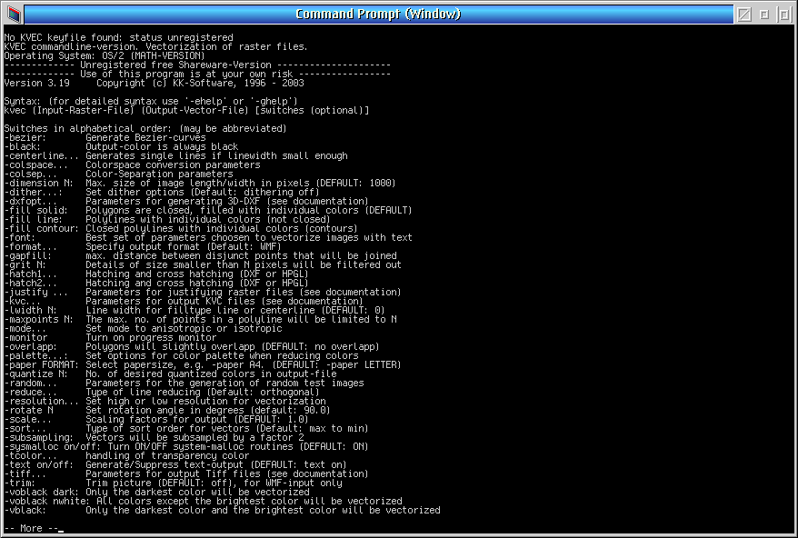


Add new comment